


6 - 3 6 - 3
MELSEC-Q
6 BASE UNIT AND EXTENSION CABLE
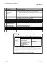
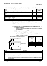
6.2 Extension Cable Specification Table
The list below shows the specifications of the extension cables which can
be used for the High Performance model QCPU system.
Type
Item
QC05B QC06B QC12B QC30B QC50B QC100B
Cable length 0.45m (1.48ft.) 0.6m (1.97ft.) 1.2m (3.93ft.) 3.0m (9.84ft.) 5.0m (16.39ft.) 10.0m (32.79ft.)
Application Connection across the main base unit and extension base unit or across the extension base units.
Weight 0.15 kg 0.16 kg 0.22 kg 0.40 kg 0.60 kg 1.11 kg
POINT
When the extension cables are used in combination, limit the overall distance
of the combined cable to 13.2 m(43.28 ft.).
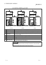
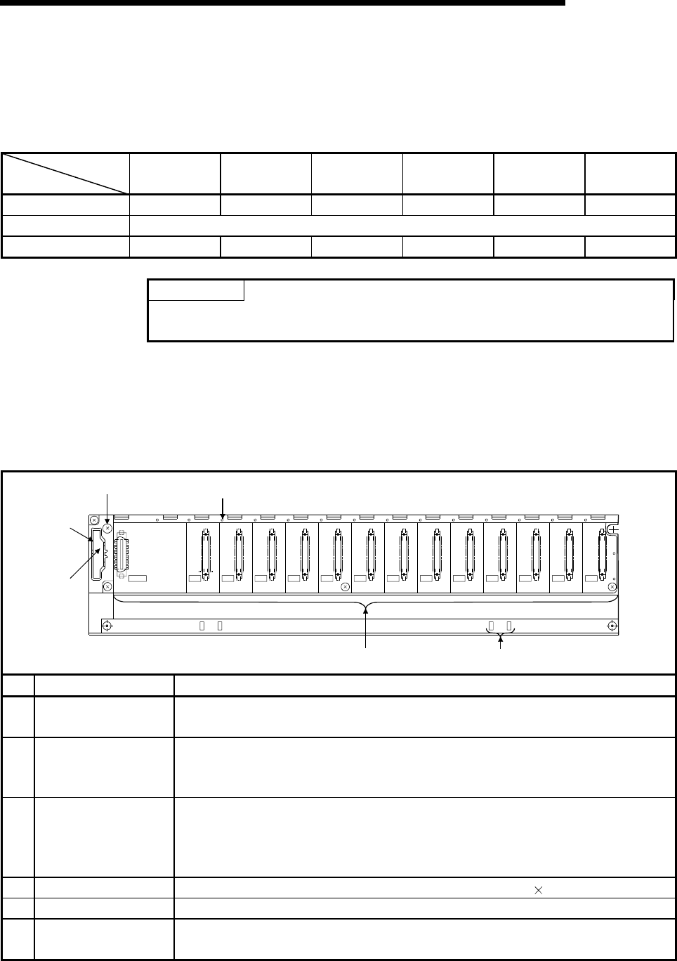
6.3 Parts Names of Base Unit
The names of the parts of the base unit are described below.
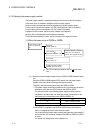
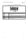
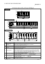
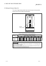
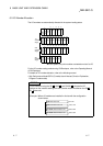
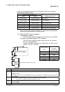
(1) Main base unit(Q33B, Q35B, Q38B, Q312B)
1)
2)
5)
4)
3) 6)
I/11I/10I/09I/08I/07I/06I/05I/04I/03I/02I/01I/00
CPU
POWER
5V
56
F6
No. Name Application
1)
Extension cable
connector
Connector for sending and receiving signals from the extension base unit, to which the
extension cables are connected.
2) Base cover
Protective cover of extension cable connector. Before an extension cable is connected,
the area of the base cover surrounded by the groove under the word "OUT" on the base
cover must be removed with a tool such as nippers.
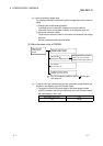
3) Module connector
Connector for installing the power supply module, CPU module, I/O modules, and
intelligent function module.
To the connectors located in the spare space where these modules are not installed, attach
the supplied connector cover or the blank cover module (QG60) to prevent entry of dirt.
4) Module fixing screw hole Screw hole for fixing the module to the base unit. Screw size:M3 12
5) Base mounting hole Hole for mounting this base unit onto the panel of the control panel (for M4 screw)
6)
DIN rail adapter
mounting hole
Hole for mounting DIN rail adapter