


Index - 1 Index - 1
INDEX
[A]
Allowable momentary power failure period ... 4- 3
AnS Series.....................................................A-12
[B]
Base unit
Extension ....................................2- 3, 6- 5, 6- 6
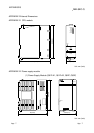
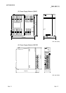
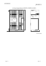
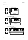
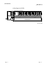
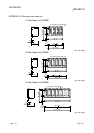
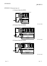
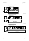
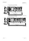
External dimensions diagram
.....App- 9 to App-13
Installation and removal
of the module................................9-14 to 9-17
Installation dimensions.............................. 9-12
Installation direction................................... 9-13
Installation position.................................... 9-12
Names of parts ........................................... 6- 3
Specifications.............................................. 6- 1
Battery
Installation................................................... 7- 6
Replacement procedure
(CPU module)........................................... 10- 6
Replacement procedure
(SRAM card)............................................. 10- 7
Replacement standard ............................. 10- 5
Boot operation ......................................4- 7,11-13
[C]
Circuit
Fail-safe ...................................................... 9- 5
System design ..................................... 9- 3,9- 4
Clock function................................................. 4- 3
Constant scan ................................................ 4- 1
Control method............................................... 4- 1
CPU
Installation and removal ............................ 9-14
Performance ............................................... 4- 1
[D]
DIN rail
~ installation adapter ................................. 9-11
Applicable .................................................. 9-11
Intervals of ~ installation screws ............... 9-11
[E]
Extension
Base unit..................................................... 6- 2
Cable ................................................. 6- 3, 9-19
Stage ....................................................2- 4,6- 7
External dimensions
CPU module...................................App- 7, 4- 3
Base unit.........................................App- 9, 6- 1
Power supply module.....................App- 7, 5- 1
[G]
GX Developer ............................................... A-12
[H]
High Performance model QCPU...........A-12,1- 1
[I]
I/O control mode .............................................4- 1
Installation and removal..................................9- 9
Intelligent function module
Direct device................................................4- 3
Limit .............................................................2- 6
Internal current consumption..........................4- 3
[L]
Latch range .....................................................4- 3
LED
"BAT." ~ is turned on.................................11- 8
"BOOT." ~ is flickering. .............................11- 9
"ERR." ~ is turned on/flickering. ...............11- 7
"MODE" ~ is not turned on. ......................11- 3
"MODE" ~ is flickering...............................11- 4
"POWER" ~ is turned off...........................11- 5
"RUN" ~ is turned off/flickering. ................11- 6
"USER" ~ is turned on. .............................11- 8
Names .........................................................4- 4
Limit.................................................................2- 6
Link direct device ............................................4- 3
[M]
Maximum number of extension stages ..........2- 4
Memory
Capacity.......................................................4- 1
Card.............................................................7- 1
[N]
Number of device I/O points...........................4- 1
Number of occupied I/O points.......................4- 1
Ind