


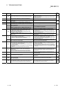
11 - 40 11 - 40
MELSEC-Q
11 TROUBLESHOOTING
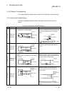
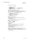
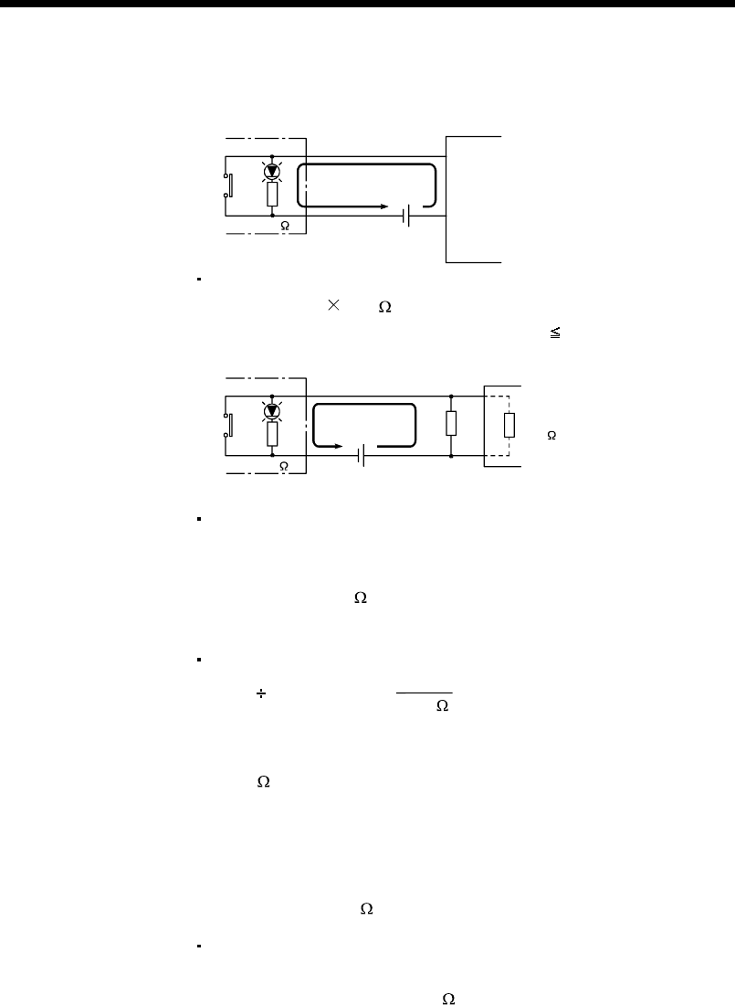
<Calculation example of Example 4>
Leakage current
2.33mA
24VDC
Input module
QX40
If a switch with an LED display
is connected to QX40 and current
of 2.33 mA is leaked.
4.7k
Voltage V
TB
across the terminal and common base is:
V
TB
= 2.33[mA] 5.6[k ] = 13[V] (Ignore the voltage drop caused by the LED.)
Because the condition for the OFF voltage (
11 [V]) is not satisfied, the input does
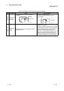
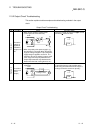
not turn off. To correct this, connect a resistor as shown below.
QX40
Current I
24VDC
Input impedance
R
4.7k
5.6k
Calculation of current for resistor R
The voltage of QX40 across the terminals must be reduced to 11 [V] or less.
The required current
(24-11[V]) ÷ 4.7[k
] = 2.77[mA]
Therefore resistor R of flowing current I of 2.77 [mA] or more must be connected.
Calculation of resistance of connected resistor R
11[V] R > 2.77[mA] -
5.6[k ]
11[V]
11[V] ÷ R > 2.77-1.96[mA]
11[V] ÷ 0.81[mA] > R
13.6[k
] > R
Resistance of the connected resistor R is obtained in the above equations.
Suppose that the resistance R is 12 [kW].
The power capacity W of the resistor during activation of the switch is:
W = (Applied voltage)
2
/ R
W = (28.8[V])
2
/12[k ]=0.069[W]
Because the resistance is selected so that the power capacity is three to five times
the actual power consumption, a third to a half [W] should be selected.
In this case, a resistor of 12 [k
] and a third to a half [W] should be connected across
the terminal and COM.