Fiber Driver
®
EM316SW-XY
PN 1288003-001, Rev D2
iii
Table of Figures
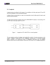
Figure 1 -- Loopback on FO1 while FO2 is in normal operation ........................................................................... 2
Figure 2 -- Dual Repeater Mode ........................................................................................................................... 5
Figure 3 -- Dual Converter Mode .......................................................................................................................... 6
Figure 4 -- Redundant Link Mode ......................................................................................................................... 7
Figure 5 -- Switching Mode ................................................................................................................................... 8
Figure 6 -- Unpacking............................................................................................................................................ 9
Figure 7 -- EM316SW-XY front panel ................................................................................................................. 10
Figure 8 -- EM316SW-XY front panel ................................................................................................................. 11
Figure 9 -- DIP switch locations .......................................................................................................................... 12
Figure 10 -- Remove the required blank panels.................................................................................................... 16
Figure 11 -- Module installation (not all chassis are shown)................................................................................. 17
Figure 12 -- Correctly inserted Fiber Driver module in a powered chassis........................................................... 17
Figure 13 -- Cleaning cartridge ............................................................................................................................. 18
Figure 14 – Contaminated fiber and clean fiber.................................................................................................... 18
Figure 15 -- SFP cleaners ..................................................................................................................................... 19
Figure 16 -- Mylar Tab on SFP Module................................................................................................................. 20
Figure 17 -- Insertion of a Mylar Tab SFP Module................................................................................................ 20
Figure 18 -- Removal of a Mylar Tab SFP Module ............................................................................................... 20
Figure 19 – Actuator/Button SFP Module ............................................................................................................. 21
Figure 20 -- Insertion of an Actuator/Button SFP Module..................................................................................... 21
Figure 21 -- Removal of an Actuator/Button SFP Module..................................................................................... 21
Figure 22 -- Bale Clasp SFP Module .................................................................................................................... 22
Figure 23 -- Insertion of a Bale Clasp SFP Module .............................................................................................. 22
Figure 24 -- Removal of a Bale Clasp SFP Module .............................................................................................. 22
Figure 25 -- EM316LNXNM-OT general commands for EM316SW-XY modules ................................................ 25


