


10 CommPlete 4000 Communications Server User Guide
Chapter 2 - Installing Your CommPlete 4000
ISI Board Cabling
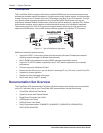
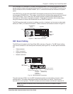
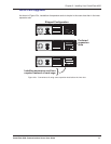
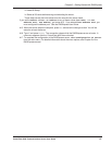
Each Intelligent Serial Interface card (ISI5634PCI/8, ISI5634UPCI/8, ISI4608PCI, ISI4608UPCI or
ISIHP-2S/2U) takes up one physical slot in the CommPlete 4000. Depending on your configuration,
you may have as many as four of these cards (see Figure 2-1). Attach the line cords (RJ-12 for
analog phone lines; RJ-45 for UPCI or ISDN phone lines) to the line connectors on the ISI card(s) at
the back of your CommPlete 4000 as shown in Figure 2-3.
ISI5634PCI/8 Board
120
RJ12 Line Jacks
MODEM
LINE
5-8
MODEM
LINE
1-4
RJ45 Line Jacks
Modem
Line
1-4
Modem
Line
5-8
ISI5634UPCI/8
Figure 2-3: ISI Board Connectors (ISI5634PCI/8 and ISI5634UPCIshown;
other MultiModem ISI cards differ)
Note: Any cables connected to the CommPlete 4000 should be shielded to reduce
interference.
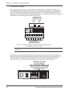
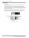
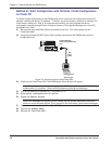
Note that the two top expansion slots share a data interrupt signal on the PCI bus. Consequently, if
both slots are used, they must be occupied with identical devices (and the device drivers must be
identical). This is a constraint of PCI bus architecture. Also, the device drivers must support
“interrupt-sharing.” The drivers for the MultiTech ISI card do support interrupt-sharing
120
Shared Interrupt
for Top Slots.
Identical Devices Required.
You can not mix PCI &UPCIcards
in these two slots, because they
use different drivers.
Figure 2-3b. Top Slots Require Identical Devices