


CommPlete 4000 Communications Server User Guide 19
Chapter 4 - Hardware removal/Replacement
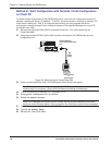
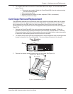
5 To re-attach cables and re-mount the CommPlete 4000, follow steps 1-4 in reverse order and
sense. That is,
a. (Two people are needed.) Attach the CommPlete 4000 to its rack enclosure using
the four mounting screws.
b. Reconnect phone cords.
c. Reconnect the SBC cables (to video, keyboard, COM1, and network).
d. Restore power when ready.
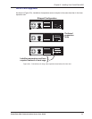
Card Cage Removal/Replacement
The steps below describe how to remove the card cage. Note that card cage removal is not always
necessary to remove or replace some components. Specifically, expansion cards can be installed
into or removed from the SBC side of the card cage without removing the card cage. However,
installing/removing an expansion card from the opposite side requires removal of the card cage (see
Figure 2-3c).
1 Remove the CommPlete 4000
from rack enclosure (two people are needed). Follow the
procedure “Disconnecting Cables and Removal from Enclosure” presented above. Summary:
after powering down the unit and disconnecting all power and signal cables, employ two people
to remove its rack-mounting screws and lift the unit out of the rack.
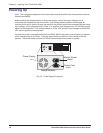
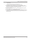
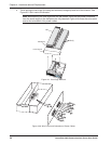
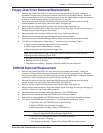
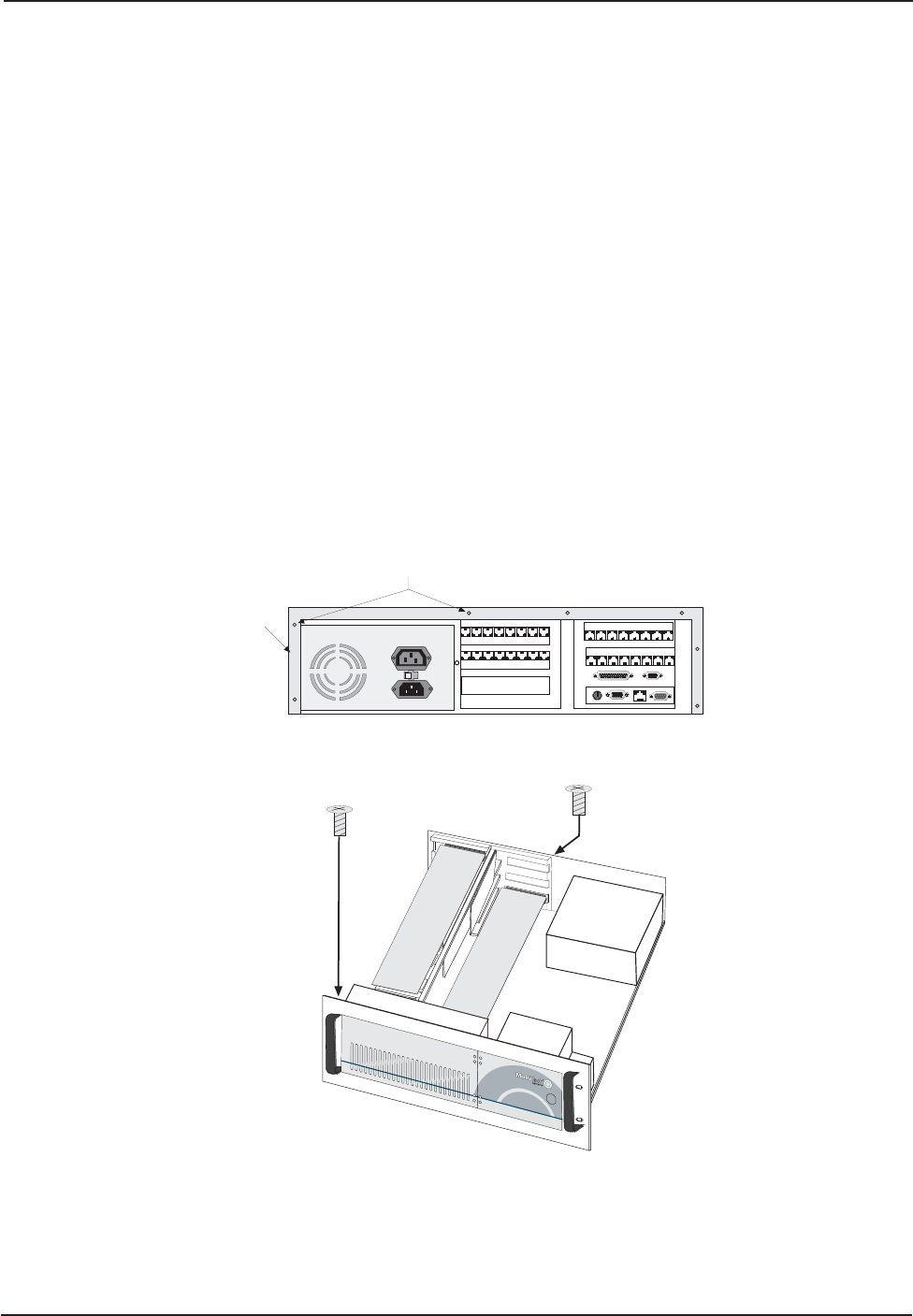
2 To remove the top cover from the CommPlete 4000
, remove the seven cover mounting screws
located in the back of the CommPlete 4000. The cover slides off the back of the chassis.
120
Cover Mounting
Screws (7)
Cover
Fig. 4-3. Cover Mounting Screws
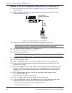
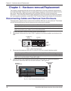
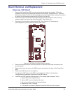
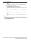
3 Remove the chassis mounting screws from the card cage. See Figure 4-4.
Chassis Mounting
Screws
B
A
N
K
1
B
A
N
K
1
M
1
M
2
M
3
M
4
S
O
C
K
E
T
7
L
O
C
K
Fig. 4-4. Chassis Mounting Screw