


20 CommPlete 4000 Communications Server User Guide
Chapter 4 - Hardware removal/ Replacement
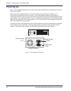
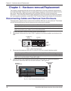
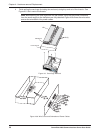
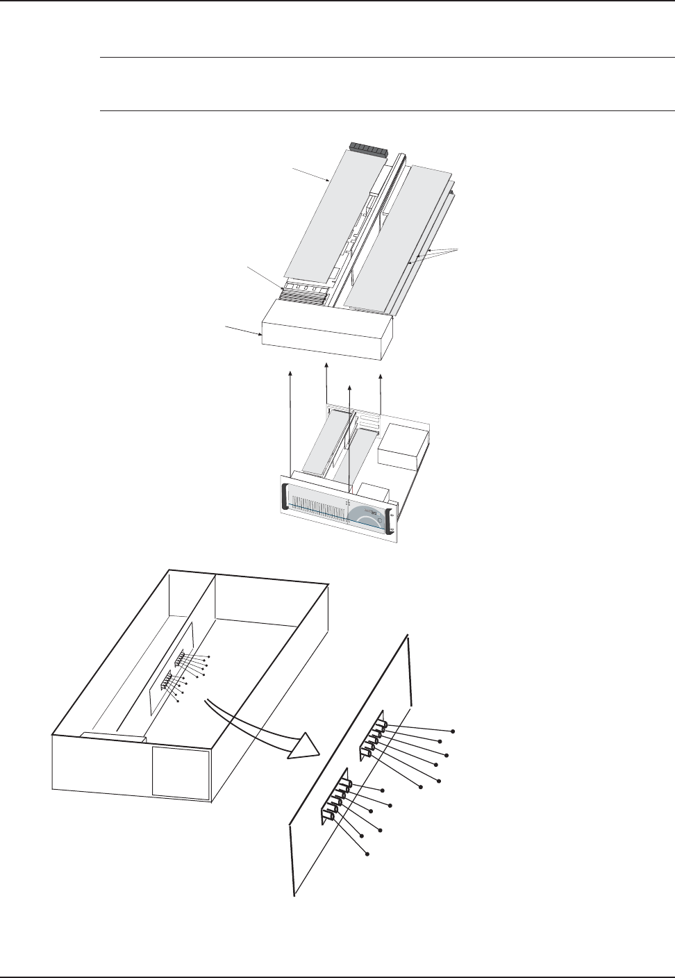
4 Finish pulling the card cage (including fan enclosure) straight up and out of the chassis. See
Figure 4-5. Set it next to the chassis.
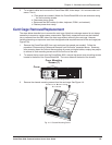
Note: Before placing the card cage back into the chassis, verify that the power connectors
from the power supply to the backplane are fully attached. Figure 4-5b shows the wire colors
and correct orientation of the power cables.
ISI (3)
SBC Board
B
A
N
K
1
SOCKET 7
L
O
C
K
M4
M3
BA
N
K
1
M2
M1
B
A
N
K
1
B
A
N
K
1
M
1
M
2
M
3
M
4
S
O
C
K
E
T
7
L
O
C
K
Fan Enclosure
ISI
Figure 4-5. Card Cage Removal
Orange
Red
Blue
Black
Black
Yellow
Red
Red
Red
Black
Black
White
CommPlete
O
range
Red
B
lu
e
B
la
ck
B
la
c
k
Y
e
llo
w
Red
Red
R
ed
B
la
c
k
B
la
c
k
W
hite
Figure 4-5b: Wire Colors and Orientation of Power Cables