


© National Instruments Corporation 4-1 SCXI-1141/1142/1143 User Manual
4
Theory of Operation
This chapter contains an overview of the SCXI-1141/1142/1143 module
and explains the operation of each functional unit of the module.
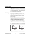
The SCXI-1141/1142/1143 module has eight software-controlled input
channels that amplify and filter signals. Each channel has an output range
of ±5 V and has an input amplifier with gains of 1, 2, 5, 10, 20, 50, and 100.
You can independently set each amplifier gain. The analog inputs are
overvoltage protected. The SCXI-1141/1142/1143 module filters are
lowpass, 8th-order elliptic, Bessel, and Butterworth filters respectively that
can have a cutoff frequency from 10 Hz to 25 kHz. All eight filters have the
same cutoff frequency. The outputs of all eight channels are available at the
rear connector.
The major components of the SCXI-1141/1142/1143 module are as
follows:
• Digital control and calibration circuitry
• Input amplifiers
• Lowpass filters
Power-Up State
When the SCXI-1141/1142/1143 module is powered up or reset through
software or the SCXI chassis reset button, the following states are defined:
• The gain of each amplifier is set to 1.
• Channel 0 is selected as the OUTPUT signal and the module defaults
to multiplexed mode.
• All filters are placed in bypass mode.
• The external clock input is disabled.
The cutoff frequency of the filters and the output clock frequency are not
defined at power-up.
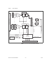
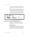
The block diagram in Figure 4-1 illustrates the key functional components
of the SCXI-1141/1142/1143 module.