


© National Instruments Corporation 11 NI 6509 User Guide and Specifications
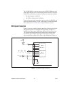
Signal Descriptions
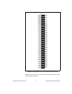
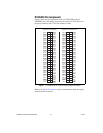
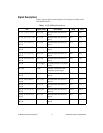
Table 1 lists the signals and descriptions for all signals available on the
NI USB-6509 device.
Table 1. NI USB-6509 Signal Descriptions
Pin Signal Name Description MSB LSB
1, 3, 5, 7, 9, 11, 13, 15 P2.<7..0> Bi-directional data lines for
port 2
P2.7 P2.0
2, 4, 6, 8, 10, 12, 14, 16 P5.<7..0> Bi-directional data lines for
port 5
P5.7 P5.0
17, 19, 21, 23, 25, 27,
29, 31
P1.<7..0> Bi-directional data lines for
port 1
P1.7 P1.0
18, 20, 22, 24, 26, 28,
30, 32
P4.<7..0> Bi-directional data lines for
port 4
P4.7 P4.0
33, 35, 37, 39, 41, 43,
45, 47
P0.<7..0> Bi-directional data lines for
port 0
P0.7 P0.0
34, 36, 38, 40, 42, 44,
46, 48
P3.<7..0> Bi-directional data lines for
port 3
P3.7 P3.0
49, 99 +5 V supply +5 Volts; provide +5 V power
source
— —
50, 100 GND Ground; connected to the
computer ground signal
— —
51, 53, 55, 57, 59, 61,
63, 65
P8.<7..0> Bi-directional data lines for
port 8
P8.7 P8.0
52, 54, 56, 58, 60, 62,
64, 66
P11.<7..0> Bi-directional data lines for
port 11
P11.7 P11.0
67, 69, 71, 73, 75, 77,
79, 81
P7.<7..0> Bi-directional data lines for
port 7
P7.7 P7.0
68, 70, 72, 74, 76, 78,
80, 82
P10.<7..0> Bi-directional data lines for
port 10
P10.7 P10.0
83, 85, 87, 89, 91, 93,
95, 97
P6.<7..0> Bi-directional data lines for
port 6
P6.7 P6.0
84, 86, 88, 90, 92, 94,
96, 98
P9.<7..0> Bi-directional data lines for
port 9
P9.7 P9.0