


© National Instruments Corporation 21 NI 6509 User Guide and Specifications
Internally, the filter uses two clocks: the sample clock and the filter clock.
The sample clock has a frequency of 48 MHz that corresponds to a period
of 20.83 ns. The filter clock is generated by a counter and has a period equal
to one half of the specified timing interval. The input signal is sampled on
each rising edge of the sample clock. However, a change in the input signal
is recognized only if it maintains its new state for at least two consecutive
rising edges of the filter clock.
The filter clock is programmable and allows you to control how long a
pulse must last to be recognized. The sample clock provides a fast sample
rate to ensure that input pulses remain constant between filter clocks.
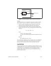
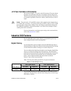
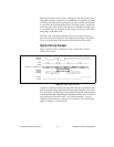
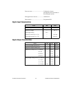
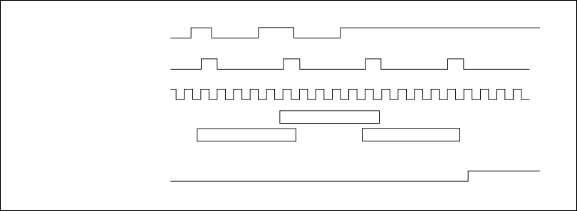
Digital Filtering Example
Figure 18 shows a filter configuration with an 208 ns filter interval
(104 ns filter clock).
Figure 18. Digital Filtering Example
In periods A and B, the filter blocks the glitches because the external signal
does not remain steadily high from one rising edge of the filter clock to the
next. In period C, the filter passes the transition because the external signal
remains steadily high. Depending on when the transition occurs, the filter
may require up to two filter clocks—one full filter interval—to pass a
transition. Figure 18 shows a rising (0 to 1) transition. The same filtering
applies to falling (1 to 0) transitions.
Sample Clock (20.83 ns)
HH HHH
HLLL H
HLLL H
A
B
C
H
H
H
External
Signal
Filter
Clock
External
Signal
Sampled
Filtered
Signal