


NI 6509 User Guide and Specifications 12 ni.com
Digital I/O
Static DIO on NI USB-6509 Devices
You can use each of the NI USB-6509 DIO lines as a static digital
input (DI) or digital output (DO) line. You can use static DIO lines to
monitor or control digital signals. Each DIO port can be configured as a
DI or DO port.
All samples of static DI lines and updates of DO lines are software-timed.
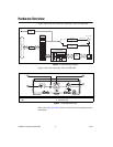
Digital I/O Circuitry
The NI USB-6509 provides 96 lines of bidirectional DIO signals,
P<0..11>.<0..7>. You can configure the direction as input or output on a
per-port basis. Each I/O line has a 100 kΩ I/O pull resistor. For more
information on the I/O pull resistor, refer to the I/O Pull-Up/Pull-Down
Resistor section.
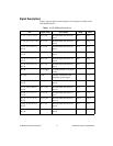
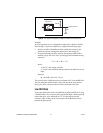
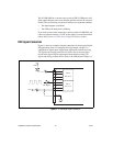
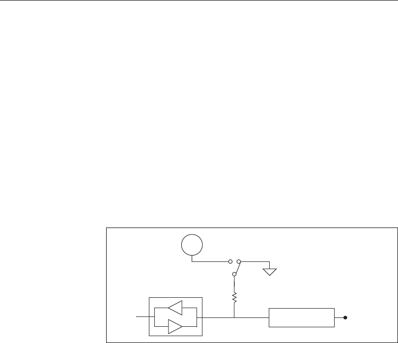
Figure 8 shows the circuitry of one DIO line.
Figure 8. NI USB-6509 Digital I/O Circuitry
The voltage input and output levels and the current drive levels of the DIO
lines are listed in the Specifications section.
I/O Protection
You should avoid ESD events and overvoltage, undervoltage, and
overcurrent fault conditions by following these guidelines.
• If you configure a DIO line as an output, do not connect it to any
external signal source, ground signal, or power supply.
• If you configure a DIO line as an output, understand the current
requirements of the load connected to these signals. Do not exceed the
specified current output limits of the DAQ device. NI has several signal
GND
I/O Protection
Transceiver
PX.Y
+5 V
100 kΩ