


NI 6509 User Guide and Specifications 14 ni.com
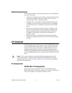
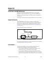
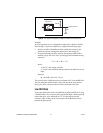
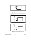
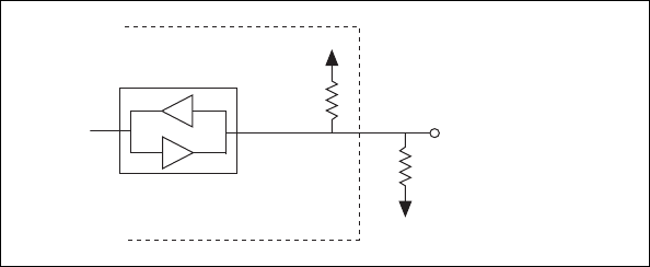
Figure 9. DIO Channel Configured for High DIO State with External Load
Example:
At power up, the device is configured for input and, by default, all DIO
lines are high. To pull one channel low, complete the following steps:
1. Install a load (R
L
). Remember that the smaller the resistance, the
greater the current consumption and the lower the voltage (V).
2. Using the following formula, calculate the largest possible load to
maintain a logic low level of 0.8 V and supply the maximum driving
current (I).
V = I * R
L
⇒ R
L
= V / I
where:
V= 0.8 V is the voltage across R
L
I = 91 μA is the maximum leakage current from the device at low
input
therefore:
R
L
= 8.8 kΩ is the 0.8 V / 91 μA
This resistor value, 8.8 kΩ, provides a maximum of 0.8 V on the DIO line.
You can substitute smaller resistor values, but they draw more current,
leaving less drive current for other circuitry connected to this line.
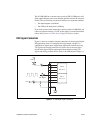
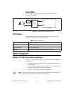
Low DIO State
If you select pulled-low mode, each DIO line is pulled to GND (0 V) using
a 100 kΩ resistor. If you want to pull a specific line high, connect a pull-up
resistor that gives you a minimum of 2 V. Use the largest possible
resistance value so that you do not use more current than necessary to
perform the pull-up task.
NI USB-6509
Digital I/O Line
100 kΩ
GND
R
L
+5 V
Transceiver