


NI 6509 User Guide and Specifications 16 ni.com
The NI USB-6509 has a current-sense circuit on VBUS (USB power rail).
If the output channels source more than the specified current, the current is
limited. The two following occurrences indicate an overcurrent condition:
• The inputs/outputs are disabled
• The LED on the back panel is blinking
If you want to increase the current drive capacity on the NI USB-6509, you
can use an optional external +12 VDC power supply. For more information,
refer to the Optional +12 VDC Power Supply Installation section.
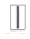
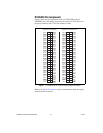
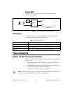
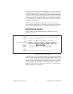
DIO Signal Connection
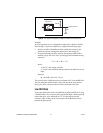
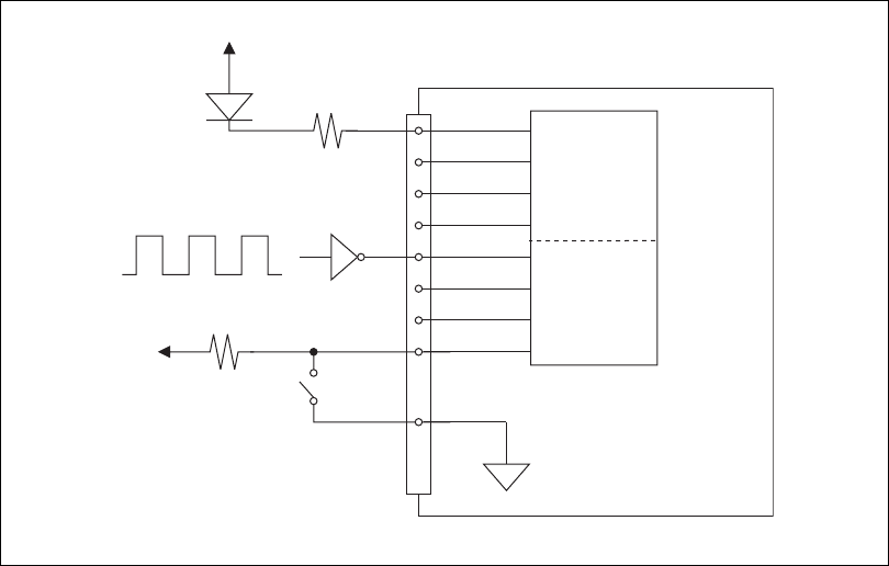
Figure 11 shows an example of signal connections for three typical digital
I/O applications. Port 0 is configured for digital output, and port 7 is
configured for digital input. Digital input applications include receiving
TTL signals and sensing external device states such as the state of the
switch in the figure. Digital output applications include sending TTL
signals and driving external devices such as the LED shown in Figure 11.
Figure 11. NI USB-6509 Signal Connections
41
43
45
47
67
69
71
73
50, 100
NI USB-6509
+5 V
+5 V
LED
P7.<7..4>
P0.<3..0>
GND
TTL Signal
Port 0
Port 7