


© National Instruments Corporation 23 NI 6509 User Guide and Specifications
Change Detection Example
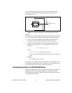
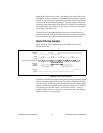
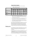
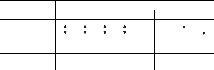
Table 4 shows a change detection example for six bits of one port.
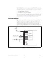
This example assumes the following line connections:
• Bits 7, 6, 5, and 4 are connected to data lines from a four-bit TTL
output device. The NI USB-6509 detects any change in the input data
so you can read the new data value.
• Bit 1 is connected to a limit sensor. The NI USB-6509 detects rising
edges on the sensor, which correspond to over-limit conditions.
• Bit 0 is connected to a switch. The software can react to any switch
closure, which is represented by a falling edge. If the switch closure is
noisy, enable digital filtering for this line.
In this example, the NI USB-6509 reports rising edges only on bit 1, falling
edges only on bit 0, and rising and falling edges on bits 7, 6, 5, and 4.
The NI USB-6509 reports no changes for bits 3 and 2. After receiving
notification of a change, you can read the port to determine the current
values of all eight lines. You cannot read the state of any lines that are
configured for change detection until the change detection interrupt occurs.
Watchdog Timer
The watchdog timer is a software configurable feature used to set critical
outputs to safe states in the event of a software failure, a system crash, or
any other loss of communication between the application and the
NI USB-6509.
When the watchdog timer is enabled, if the NI USB-6509 does not receive
a watchdog reset software command within the time specified for the
watchdog timer, the outputs go to a user-defined safe state and remain in
that state until the watchdog timer is disarmed by the application and new
values are written, the NI USB-6509 is reset, or the computer is restarted.
Table 4. Change Detection Example
Bit
7 6 5 4 3 2 1 0
Changes to detect — —
Enable rising-edge
detection
yes yes yes yes no no yes no
Enable falling-edge
detection
yes yes yes yes no no no yes