


© National Instruments Corporation 17 NI 6509 User Guide and Specifications
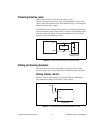
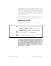
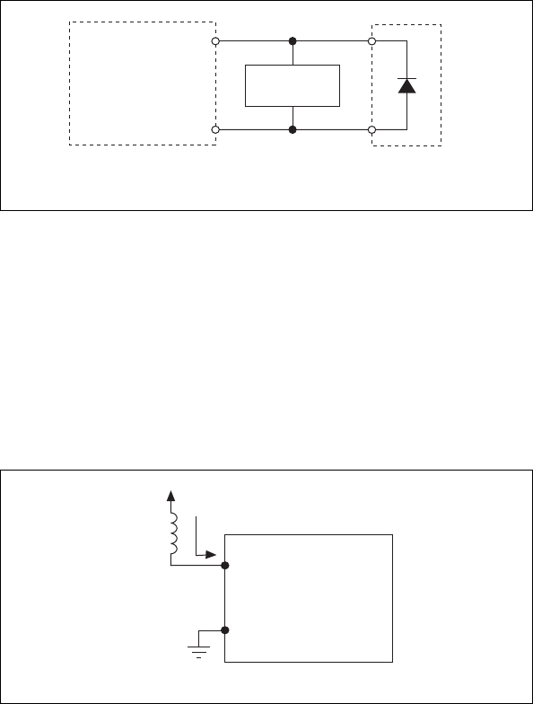
Protecting Inductive Loads
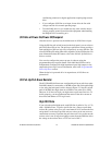
When inductive loads are connected to outputs, a large
counter-electromotive force may occur at switching time because of the
energy stored in the inductive load. These flyback voltages can damage the
outputs and/or the power supply.
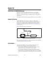
To limit these flyback voltages at the inductive load, install a flyback diode
across the inductive load. For best results, mount the flyback diode within
18 inches of the load. Figure 12 shows an example of using an external
flyback diode to protect inductive loads.
Figure 12. Limiting Flyback Voltages at the Inductive Load
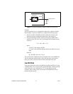
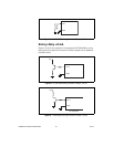
Sinking and Sourcing Examples
The following sections provide examples of driving a relay less than
24 mA, driving a relay greater than 24 mA, and driving solid-state relays.
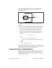
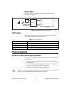
Driving a Relay <24 mA
Figures 13 and 14 show examples of connecting the NI USB-6509 to a
relay that does not require more than 24 mA of current.
Figure 13. NI USB-6509 Sinking Connection Example, <24 mA
GND
Load
NI USB-6509
Flyback Diode for
Inductive Loads
PX.Y
GND
NI USB-6509
Vcc
PX.Y