


© National Instruments Corporation 19 NI 6509 User Guide and Specifications
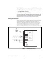
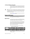
Driving SSRs
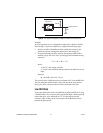
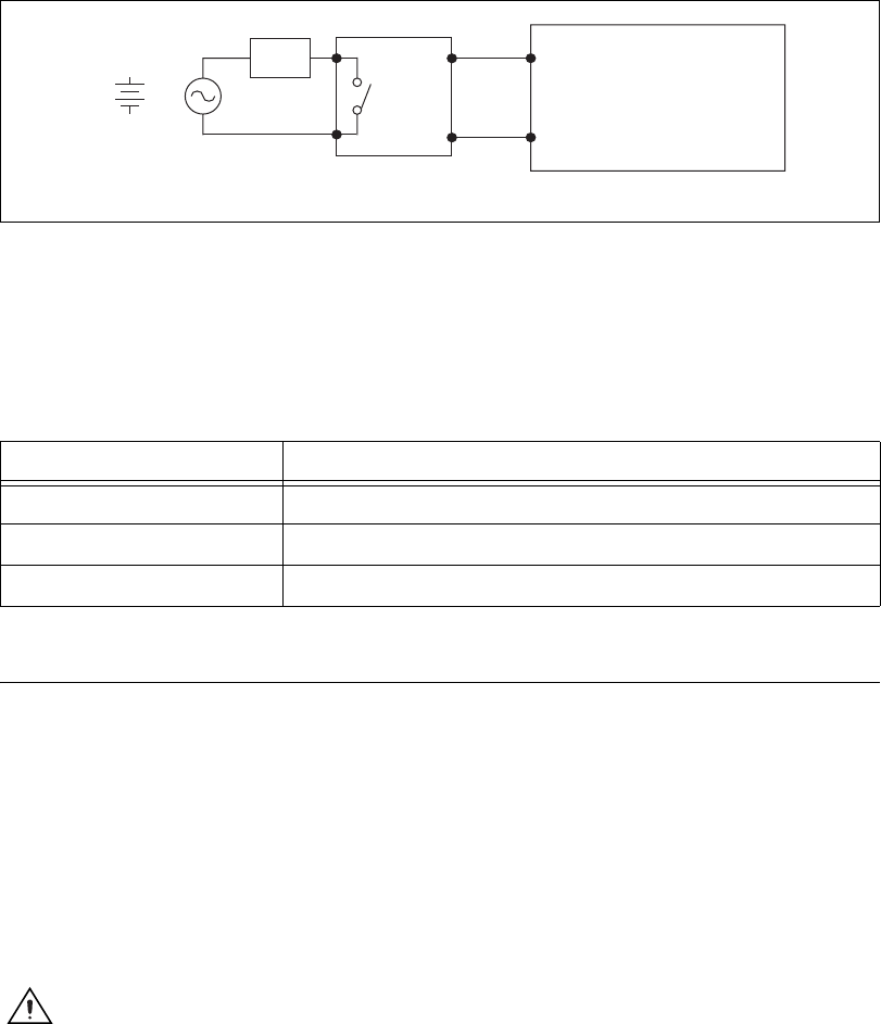
Figure 17 shows an example of connecting the NI USB-6509 to a
solid-state relay (SSR).
Figure 17. NI USB-6509 SSR Connection Example
LED Indicator
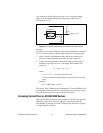
The LED indicator, located on the device back panel, indicates device
status. Table 2 shows the behavior of the LED.
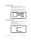
Power Connection
Optional +12 VDC Power Supply Installation
To install a +12 VDC power supply into the NI USB-6509, complete the
following steps:
1. Ensure that the device is powered off by unplugging the USB cable
from the device.
2. After the device is powered off and unplugged, remove the plastic cap
on the DC jack, located on the device back panel.
3. Plug the +12 VDC power supply into the DC jack.
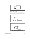
Caution Do not remove external +12 VDC power supply when the device is powered on.
Doing so may reboot the NI USB-6509 and cause device damage.
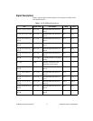
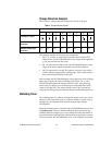
Table 2. PWR/ACT LED Status
LED State Device Status
Not lit Device not powered or in suspend state
On, not blinking Operating normally
Blinking Device error—USB power budget possibly exceeded
SSR
GND
Load
NI USB-6509
+
_
or
ACDC
PX.Y