


© National Instruments Corporation 13 NI 6509 User Guide and Specifications
conditioning solutions for digital applications requiring high current
drive.
• If you configure a DIO line as an input, do not drive the line with
voltages outside of its normal operating range.
• Treat the DAQ device as you would treat any static sensitive device.
Always properly ground yourself and the equipment when handling
the DAQ device or connecting to it.
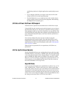
I/O State at Power-On/Power-Off/Suspend
After the device is powered on, the default state of all I/O lines is input.
Using the I/O line pull switch located on the back panel, you can select to
pull all I/O lines high or low. The pull-up or pull-down resistor provides a
weak pull-high or pull-low logic level, respectively, on every I/O line. The
selected I/O line pull setting takes effect regardless of the I/O direction. For
more information about this feature, refer to the I/O Pull-Up/Pull-Down
Resistor section.
You can also configure the power-up state in software using the
programmable power-up state feature. Each individual I/O line can be
independently configured for high-impedance input, high output, or low
output after power-up. For more information, refer to the Programmable
Power-Up States section.
When the device is powered off or in suspend state, all I/O lines are
powered off.
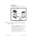
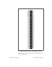
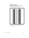
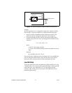
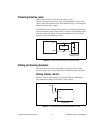
I/O Pull-Up/Pull-Down Resistor
The NI USB-6509 facilitates user-configurable pull-up or pull-down tasks.
Each DIO channel is connected to a 100 kΩ resistor and can be pulled high
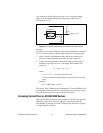
or low using the back-panel switch, shown in Figure 5. Using this switch
pulls all 96 DIO lines high when set to HIGH or low when set to LOW.
However, if all lines are high, you might want to pull some lines low. To
do this properly, you must understand the nature of the drive current on
those lines and adhere to TTL-logic levels.
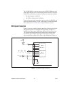
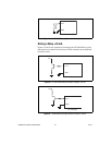
High DIO State
If you select the pulled-high mode, each DIO line is pulled to Vcc (+5 V)
with a 100 kΩ resistor. To pull a specific line low, connect a pull-down
resistor (R
L
) whose value gives you a maximum of 0.8 V between the line
and ground. Use the largest possible resistor so that you do not use more
current than necessary to perform the pull-down task. Also, make sure the
resistor value is not so large that leakage current from the DIO line drives
the voltage at the resistor above a TTL low level of 0.8 V.