


Chapter 2 Hardware Overview of the NI 7831R
© National Instruments Corporation 2-11 NI 7831R User Manual
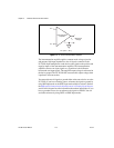
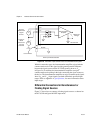
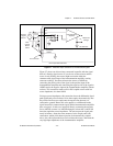
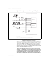
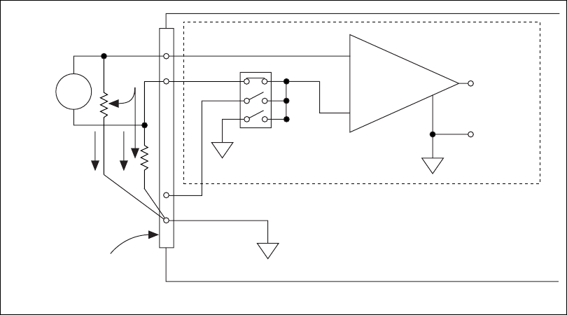
Figure 2-7. Differential Input Connections for Nonreferenced Signals
Figure 2-7 shows two bias resistors connected in parallel with the signal
leads of a floating signal source. If you do not use the resistors and the
source is truly floating, the source might not remain within the
common-mode signal range of the instrumentation amplifier, causing
erroneous readings. You must reference the source to AIGND by
connecting the positive side of the signal to the positive input of the
instrumentation amplifier and connecting the negative side of the signal to
AIGND and to the negative input of the instrumentation amplifier without
resistors. This connection works well for DC-coupled sources with low
source impedance, less than 100 Ω.
For larger source impedances, this connection leaves the differential signal
path significantly out of balance. Noise that couples electrostatically onto
the positive line does not couple onto the negative line because it is
connected to ground. Hence, this noise appears as a differential-mode
signal instead of a common-mode signal, and the instrumentation amplifier
does not reject it. In this case, instead of directly connecting the negative
line to AIGND, connect it to AIGND through a resistor that is about 100
times the equivalent source impedance. The resistor puts the signal path
nearly in balance. About the same amount of noise couples onto both
connections, which yields better rejection of electrostatically coupled
noise. Also, this input mode does not load down the source, other than the
very high-input impedance of the instrumentation amplifier.
Bias
Resistors
(see text)
DIFF Input Mode Selected
–
+
–
+
AISENSE
AIGND
V
m
Measured
Voltage
Instrumentation
Amplifier
x8 Channels
AI+
AI–
–
+
Floating
Signal
Source
Bias
Current
Return
Paths
V
s
I/O Connector