


Chapter 2 Hardware Overview of the NI 7831R
NI 7831R User Manual 2-22 ni.com
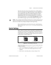
4. Reinsert the NI 7831R into the PXI/CompactPCI chassis or PCI
computer. Refer to the Installing the Hardware section of the Getting
Started with the NI 7831R document for installation instructions.
5. Plug in and power on the PXI/CompactPCI chassis or PCI computer.
After completing this procedure, a VI stored in flash memory does not load
to the FPGA at power-on. You can use software to configure the NI 7831R
if necessary. To return to the defaults of loading from flash memory, repeat
the previous procedure but return switch 1 to the OFF position in step 3.
You can use this switch to enable/disable the ability to load from flash. In
addition to this switch, you must configure the device with the software to
autoload.
Note When the NI 7831R is powered on with switch 1 in the ON position, the analog
circuitry does not return properly calibrated data. Move the switch to the ON position only
while you are using software to reconfigure the NI 7831R for the desired power-up
behavior. Afterward, return switch 1 to the OFF position.
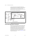
Power Connections
Two pins on each I/O connector supply 5 V from the computer power
supply using a self-resetting fuse. The fuse resets automatically within a
few seconds after the overcurrent condition is removed. The +5V pins are
referenced to DGND and can power external digital circuitry. The
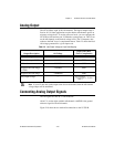
NI 7831R has the following power rating:
+4.50 to +5.25 VDC at 1 A (250 mA max per +5V pin, 1 A max total for
all +5V lines on the device)
Caution Do not connect the +5V power pins directly to analog or digital ground or to any
other voltage source on the NI 7831R or any other device under any circumstance. Doing
so can damage the NI 7831R and the computer. NI is not liable for damage resulting from
such a connection.