


Chapter 2 Hardware Overview of the NI 7831R
© National Instruments Corporation 2-21 NI 7831R User Manual
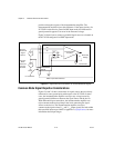
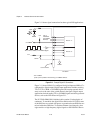
The left local bus lines from the left peripheral slot of a PXI backplane
(Slot 2) are routed to the star trigger lines of up to 13 other peripheral slots
in a two-segment PXI system. This configuration provides a dedicated,
delay-matched trigger signal between the first peripheral slot and the
other peripheral slots for precise trigger timing signals. For example, an
NI PXI-7831R in Slot 2 can send an independent trigger signal to each
device plugged into Slots <3..15> using the PXI/LBLSTAR<0..12>. Each
device receives its trigger signal on its own dedicated star trigger line.
Caution Do not configure the NI 7831R and another device to drive the same physical star
trigger line simultaneously. Such signal driving can damage the NI 7831R and the other
device. NI is not liable for any damage resulting from such signal driving.
Refer to the PXI Hardware Specification Revision 2.1 and PXI Software
Specification Revision 2.1 at
www.pxisa.org for more information about
PXI triggers.
Switch Settings
Refer to Figure 2-2 for the location of switch SW1 on the NI PXI-7831R
and Figure 2-3 for the location of switch SW1 on the NI PCI-7831R. For
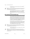
normal operation, switch 1 is in the OFF position. To prevent a VI stored
in flash memory from loading to the FPGA at power up, move switch 1 to
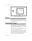
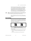
the ON position, as shown in Figure 2-12.
Figure 2-12. Switch Settings on Switch SW1
Complete the following steps to prevent a VI stored in flash memory from
loading to the FPGA:
1. Power off and unplug the PXI/CompactPCI chassis or PCI computer.
2. Remove the NI 7831R from the PXI/CompactPCI chassis or PCI
computer.
3. Move switch 1 to the ON position, as shown in Figure 2-12b.
123
ON
a. Normal Operation (Default)
123
ON
b. Prevent VI From Loading