


Chapter 2 Hardware Overview of the NI 7831R
NI 7831R User Manual 2-16 ni.com
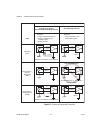
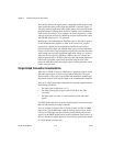
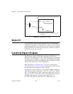
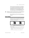
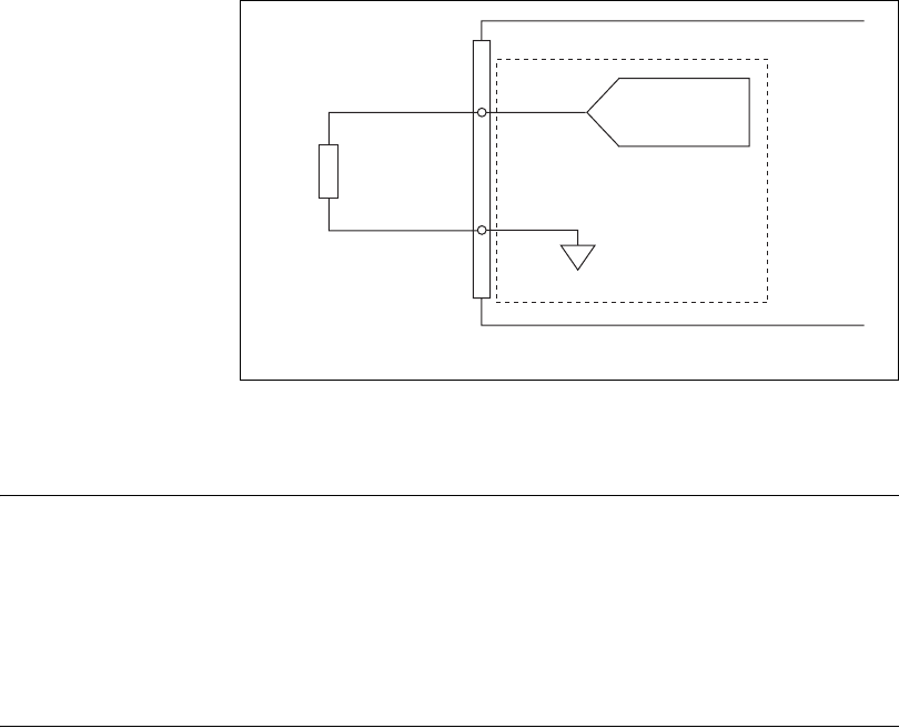
Figure 2-10. Analog Output Connections
Digital I/O
The NI 7831R has 96 bidirectional DIO lines that you can individually
configure for either input or output. When the system powers on, the DIO
lines are high-impedance. To set another power-on state, you can configure
the NI 7831R to load a VI when the system powers on. This VI can then set
the DIO lines to any power-on state.
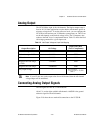
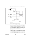
Connecting Digital I/O Signals
The DIO signals on the NI 7831R MIO connector are DGND and
DIO<0..15>. The DIO signals on the NI 7831R DIO connector are DGND
and DIO<0..39>. The DIO<0..n> signals make up the DIO port and DGND
is the ground reference signal for the DIO port. The NI 7831R has one MIO
and two DIO connectors for a total of 96 DIO lines.
Refer to Figure B-1, NI 7831R Connector Locations, and Figure B-2,
NI 7831R I/O Connector Pin Assignments, for the connector locations and
the I/O connector pin assignments on the NI 7831R.
The DIO lines on the NI 7831R are TTL-compatible. When configured as
inputs, they can receive signals from 5 V TTL, 3.3 V LVTTL, 5 V CMOS,
and 3.3 V LVCMOS devices. When configured as outputs, they can send
signals to 5 V TTL, 3.3 V LVTTL, and 3.3 V LVCMOS devices. Because
the digital outputs provide a nominal output swing of 0 to 3.3 V
(3.3 V TTL), the DIO lines cannot drive 5 V CMOS logic levels.
Load
VOUT 0
+
–
AOGND0
x8 Channels
NI 7831R
AO0
Channel 0