


Chapter 2 Hardware Overview of the NI 7831R
© National Instruments Corporation 2-17 NI 7831R User Manual
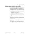
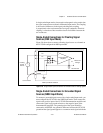
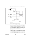
To interface to 5 V CMOS devices, you must provide an external pull-up
resistor to 5 V. This resistor pulls up the 3.3 V digital output from the
NI 7831R to 5 V CMOS logic levels. Refer to Appendix A, Specifications,
for detailed DIO specifications.
Caution Exceeding the maximum input voltage ratings, listed in Table B-2, NI 7831R I/O
Signal Summary, can damage the NI 7831R and the computer. NI is not liable for any
damage resulting from such signal connections.
Caution Do not short the DIO lines of the NI 7831R directly to power or to ground. Doing
so can damage the NI 7831R by causing excessive current to flow through the DIO lines.
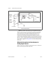
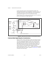
You can connect multiple NI 7831R digital output lines in parallel to
provide higher current sourcing or sinking capability. If you connect
multiple digital output lines in parallel, your application must drive all of
these lines simultaneously to the same value. If you connect digital lines
together and drive them to different values, excessive current can flow
through the DIO lines and damage the NI 7831R. Refer to Appendix A,
Specifications, for more information about DIO specifications.