


Chapter 2 Hardware Overview of the NI 7831R
© National Instruments Corporation 2-19 NI 7831R User Manual
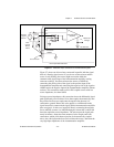
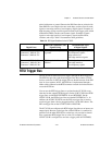
paired with power or ground. Because the DIO lines that are twisted with
other DIO lines can couple noise onto each other, use these lines for static
signals or non-edge-sensitive, low-frequency digital signals. Examples of
high-frequency or edge-sensitive signals include clock, trigger, pulse-width
modulation (PWM), encoder, and counter signals. Examples of static
signals or non-edge-sensitive, low-frequency signals include LEDs,
switches, and relays. Table 2-4 summarizes these guidelines.
RTSI Trigger Bus
The NI 7831R can send and receive triggers through the RTSI trigger bus.
The RTSI bus provides eight shared triggers lines that connect to all the
devices on the bus. In PXI, the trigger lines are shared between all the PXI
slots in a bus segment. In PCI, the RTSI bus is implemented through a
ribbon cable connected to the RTSI connector on each device that needs to
access the RTSI bus.
You can use the RTSI trigger lines to synchronize the NI 7831R to any
other device that supports RTSI triggers. On the NI PCI-7831R, the RTSI
trigger lines are labeled RTSI/TRIG<0..6> and RTSI/OSC. On the
NI PXI-7831R, the RTSI trigger lines are labeled PXI/TRIG<0..7>. In
addition, the NI PXI-7831R can use the PXI star trigger line to send or
receive triggers from a device plugged into Slot 2 of the PXI chassis. The
PXI star trigger line on the NI PXI-7831R is PXI/STAR.
The NI 7831R can configure each RTSI trigger line either as an input or an
output signal. Because each trigger line on the RTSI bus is connected in
parallel to all the other RTSI devices on the bus, only one device should
drive a particular RTSI trigger line at a time. For example, if one
NI PXI-7831R is configured to send out a trigger pulse on PXI/TRIG0,
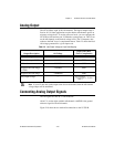
Table 2-4. DIO Signal Guidelines for the NI 7831R
Digital Lines
SH68-C68-S Shielded Cable
Signal Pairing
Recommended Types
of Digital Signals
Connector 0, DIO<0..7>;
Connector 1, DIO<0..27>;
Connector 2, DIO<0..27>
DIO line paired with power
or ground
All types—high-frequency or
low-frequency signals,
edge-sensitive or
non-edge-sensitive signals
Connector 0, DIO<8..15>;
Connector 1, DIO<28..39>;
Connector 2, DIO<28..39>
DIO line paired with another
DIO line
Static signals or
non-edge-sensitive,
low-frequency signals