


Appendix B Connecting I/O Signals
© National Instruments Corporation B-3 NI 7831R User Manual
.
Caution Connections that exceed any of the maximum ratings of input or output signals
on the NI 7831R can damage the NI 7831R and the computer. Maximum input ratings for
each signal are in the Protection column of Table B-2. NI is not liable for any damage
resulting from such signal connections
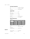
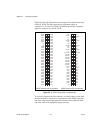
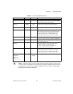
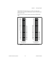
Table B-1. I/O Connector Signal Descriptions
Signal Name Reference Direction Description
+5V DGND Output +5 VDC Source—These pins supply 5 V from the computer
power supply using a self-resetting 1 A fuse. No more than
250 mA should be pulled from a single pin.
AI<0..7>+ AIGND Input Positive input for Analog Input channels 0 through 7.
AI<0..7>– AIGND Input Negative input for Analog Input channels 0 through 7.
AIGND — — Analog Input Ground—These pins are the reference point for
single-ended measurements in RSE configuration and the
bias current return point for differential measurements.
All three ground references—AIGND, AOGND, and
DGND—are connected to each other on the NI 7831R.
AISENSE AIGND Input Analog Input Sense—This pin serves as the reference node
for AI <0..7> when the device is configured for NRSE mode.
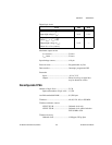
AO<0..7> AOGND Output Analog Output channels 0 through 7. Each channel can
source or sink up to 2.5 mA.
AOGND — — Analog Output Ground—The analog output voltages
are referenced to this node. All three ground
references—AIGND, AOGND, and DGND—are
connected to each other on the NI 7831R.
DGND — — Digital Ground—These pins supply the reference for the
digital signals at the I/O connector and the 5 V supply.
All three ground references—AIGND, AOGND, and
DGND—are connected to each other on the NI 7831R.
DIO<0..15>
Connector 0
DIO<0..39>
Connector <1..2>
DGND Input or
Output
Digital I/O signals.