


Chapter 2 Hardware Overview of the NI 7831R
NI 7831R User Manual 2-18 ni.com
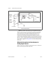
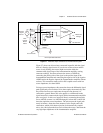
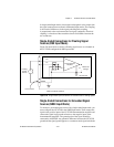
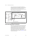
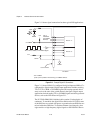
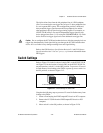
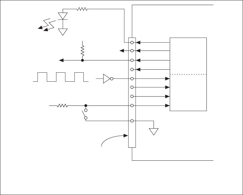
Figure 2-11 shows signal connections for three typical DIO applications.
Figure 2-11. Example Digital I/O Connections
Figure 2-11 shows DIO<0..3> configured for digital input and DIO<4..7>
configured for digital output. Digital input applications include receiving
TTL, LVTTL, CMOS, or LVCMOS signals and sensing external device
states, such as the state of the switch shown in the figure. Digital output
applications include sending TTL or LVCMOS signals and driving external
devices, such as the LED shown in Figure 2-11.
The NI 7831R SH68-C68-S shielded cable contains 34 twisted pairs of
conductors. To maximize the digital I/O available on the NI 7831R, some
of the DIO lines are twisted with power or ground and some DIO lines are
twisted with other DIO lines. To obtain maximum signal integrity, place
edge-sensitive or high-frequency digital signals on the DIO lines that are
*
3.3 V CMOS
†
Use a pull-up resistor when driving 5 V CMOS devices.
LED
TTL, LVTTL, CMOS, or LVCMOS Signal
+5 V
Switch
I/O Connector
DGND
NI 7831R
DIO<0..3>
DIO<4..7>
+5 V
5 V CMOS
†
TTL or
LVCMOS
*
Compatible
Devices
DGND