


11
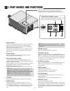
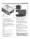
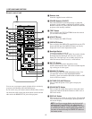
1.PART NAMES AND FUNCTIONS
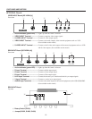
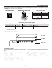
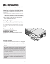
The combination of the rotary switch and the jumper pins allows the projector to accept VIDEO signals. Note that this board cannot
accept RGB signals when board is set to VIDEO input.
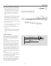
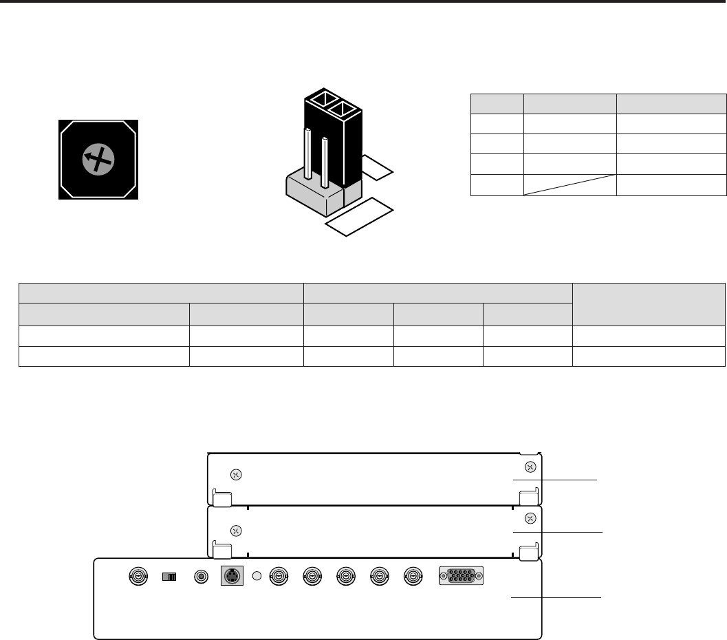
Rotary switch (S1001)
5
4
3
2
1
0
9
8
7
6
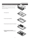
SLOT FOR OPTIONAL MODULE
Corresponding slot number
You can also select the input signal directly by pressing the INPUT “1” through “10” button. In this case INPUT buttons function as
follows:
1) When the slot A(Mother board) is selected:
INPUT 1 ...... RGB input
INPUT 2 ...... VIDEO input
INPUT 3 ...... S-VIDEO input
2) When the slot B (optional board) is selected:
When VIDEO board installed When RGB board installed
INPUT 4 ...... VIDEO input INPUT 4 ...... RGB input
INPUT 5 ...... S-VIDEO input
3) When the slot C (optional board) is selected:
When VIDEO board installed When RGB board installed
INPUT 7 ...... VIDEO input INPUT 7 ...... RGB input
INPUT 8 ...... S-VIDEO input
Input
VIDEO input
Option
RGB input
Not used
Mark
VIDEO
OPTION
RGB
No.
0
1
3
2, 4-9
Jumper (S1002, S1003, S1004)
VIDEO
4
3
2
RGB
Rotary Switch(S1001)
0
3
Jumpers
(2, 3) Short
(1, 2) Short
R terminal
VIDEO
R
G terminal
Y
G
B terminal
C
B
Board Identification
VIDEO
RGB
Input Signal
Setting of Rotary switch and Jumpers
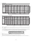
Table for Setting Rotary Switch and Jumpers.
Setting of Rotary switch
*1 ) No 1 is for future system expansion.
*2) No 3 is factory preset.
*1
*2
*
* indicates factory preset.
INPUT B slot
INPUT C slot
INPUT A slot
VIDEO BNC RCA VIDEO S-VIDEO R/Cr G/Y B/Cb H/HV V
OSD OUT