


9
POWER ON/OFF
OFF ON
IN OUT
POWER STANDBYRCREADY
INDICATOR
REMOTE2
IN OUT
OPTIONREMOTE1
VIDEO BNC RCA VIDEO S-VIDEO R/Cr G/Y B/Cb H/HV V OSD OUT
LAMP
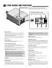
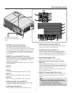
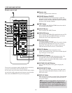
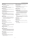
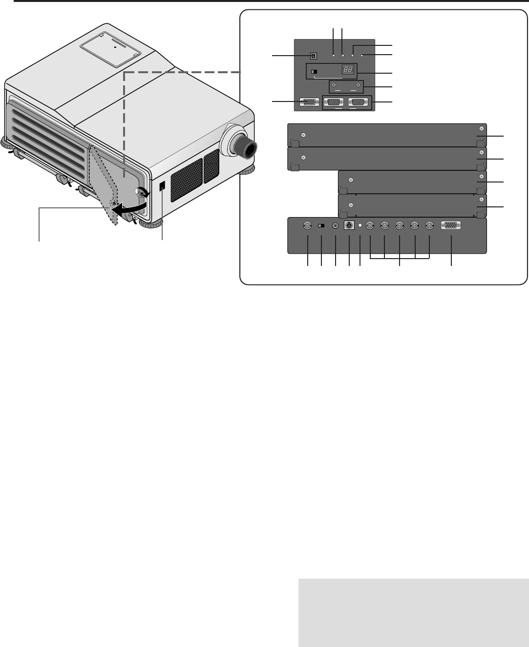
1.PART NAMES AND FUNCTIONS
B OPTION Connectors (D-Sub 9-pin)
For system expansion such as PC-control.
IN: connect to the external equipment such as PC.
OUT: for daisy-chaining multiple projectors and operating
them with the same external equipment. To do so, connect
to a second projector’ s IN terminal to relay the input at
the IN terminal of the first projector until all the projectors
are connected.
C REMOTE 1 Connector (Mini D-Sub 15-pin)
This terminal allows external control of the projector from
either the Switcher or from an external control. When the
Switcher is used, connect to the REMOTE 1 terminal on
the back of the Switcher.
NOTE: The ISS-6020/ISS-6020G Switcher is compatible
with this projector.
D INPUT E
Not used.
E INPUT D
Used for the factory-installed video processor only.
F INPUT C
Slot for adding optional RGB or video input cards.
G INPUT B
Slot for adding optional RGB or video input cards.
H VIDEO Input BNC Terminal (INPUT A)
Connect to the BNC video output of the external equip-
ment such as a VCR or laser disk player.
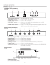
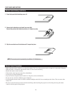
I VIDEO Input Select Switch
Selects VIDEO input between BNC and RCA type.
Loosen the screw by turning
and open to access the terminal
panel.
J VIDEO Input RCA Terminal (INPUT A)
Connect to the RCA video output of the external equip-
ment such as a VCR or laser disk player.
K S-VIDEO Input Terminal (INPUT A)
Connect to the S-video output of the external equipment
such as a VCR with an S-video output.This terminal
allows switching between S2 and S1 VIDEO input modes.
See the “S-Video Mode” section for more information.
L Active Indicator (green LED)
Lights up when the INPUT A slot is selected.
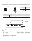
M R/Cr, G/Y, B/Cb, H H/V and V Input Terminals
(INPUT A)
Connect R,G,B,H (Horizontal sync) and V (Vertical sync)
outputs of the external equipment such as the Switcher). If
using a component with a combined sync (SYNC)output,
connect it to the H/V terminal.
Connect component video outputs of the external equip-
ment such as DVD player.
N OSD OUT Connector (Mini D-Sub 15-pin)
Outputs on-screen information. You can use this connec-
tor to loop your on-screen information to an external
monitor.
NOTE:
1)A picture may be distorted or no picture may appear
when any one of the following procedures is performed:
* An SXGA signal is input to the projector.
* A High-refresh signal is input to the projector.
2)Some types of monitor may display no image on the screen.
55
55
5
66
66
6
AA
AA
A
BB
BB
B
CC
CC
C
00
00
0
99
99
9
88
88
8
77
77
7
DD
DD
D
EE
EE
E
FF
FF
F
GG
GG
G
HH
HH
H
II
II
I
JJ
JJ
J
KK
KK
K
LL
LL
L
MM
MM
M
NN
NN
N
22
22
2