


22
2.INSTALLATION
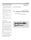
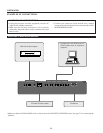
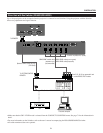
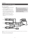
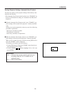
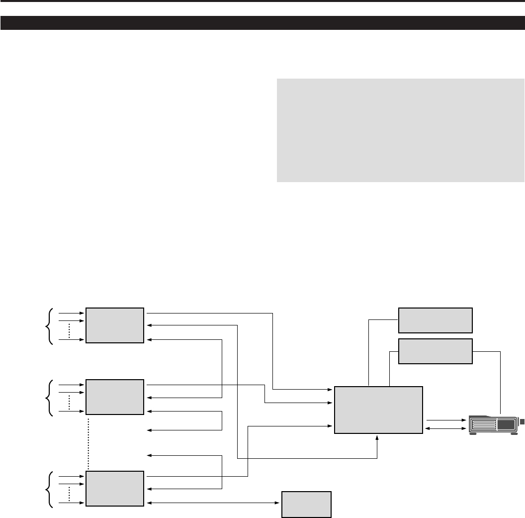
When Used with Two or More Switchers (100 Inputs)
Up to 100 inputs can be accepted using the Switcher.
How to make connections:
1 Connect the REMOTE 1 terminal of the master Switcher
to the REMOTE 1 of the projector using the optional
control cable (15p-15p/CTL-6010).
2 Next connect the REMOTE 2 terminal of the master
Switcher to the REMOTE 1 terminal of the first slave
Switcher using the same optional control cable as men-
tioned above. Third, connect the REMOTE 2 terminal of
the first slave to the REMOTE 1 of the second slave, and
the REMOTE 2 terminal of the second slave to the
REMOTE 1 terminal of the third slave (— and the
REMOTE 2 of the ninth slave to the REMOTE 1 of the
tenth slave). Connect all the Switchers with optional
control cables.
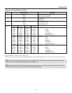
• Make sure that the SW2 LEVEL mode is selected from the CONNECT CONDITION menu. See page 71 for the information in
detail.
• Refer to the user’s manual accompanying the Switcher.
• Cables mentioned are not included with the projector.
NOTE:
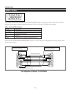
• Be sure to set all the slide switches (S8603) of the
Switcher to RS-422 positions. Set the one on the last slave
Switcher to the appropriate position to match the con-
nected equipment such as a personal computer. (RS-422/
RS-232C for PC control of projector)
• Set the DIP switch S8601 of the Switcher.
OPTION (PC)
MASTER
SWITCHER
REMOTE
CONTROL
OPTION
(PC)
SLAVE 1
SLAVE 2
SLAVE 10
10 inputs
10 inputs
10 inputs
Signal Switcher
Signal
REMOTE 1
REMOTE 2
Signal
REMOTE 1
REMOTE 2
REMOTE 1SLAVE 3
SLAVE 9
Signal
REMOTE 1
REMOTE 2
REMOTE 2
To SLOT 1
To SLOT 2
To SLOT 10
To REMOTE 2
REMOTE 1
Signal
REMOTE
Projector