


Making the Physical Connections 3-3
CC
CC
oo
oo
nn
nn
nn
nn
ee
ee
cc
cc
tt
tt
tt
tt
hh
hh
ee
ee
rr
rr
oo
oo
uu
uu
tt
tt
ee
ee
rr
rr
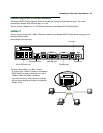
Identify the connectors and switches on the back panel and attach the necessary Netopia Router cables.
RR
RR
55
55
11
11
00
00
00
00
SS
SS
ee
ee
rr
rr
ii
ii
aa
aa
ll
ll
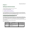
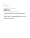
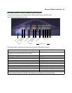
The figure below displays the back of the Netopia R5100 Serial Router.
Netopia R5100 back panel
RR
RR
55
55
22
22
00
00
00
00
DD
DD
DD
DD
SS
SS
aa
aa
nn
nn
dd
dd
RR
RR
55
55
33
33
00
00
00
00
TT
TT
11
11
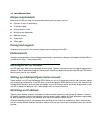
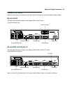
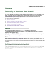
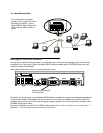
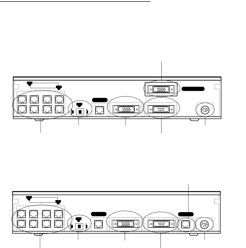
The figure below displays the back of the Netopia R5200 DDS or R5300 T1 Router.
Netopia R5200/5300 back panel
Note: For simplicity, the remainder of this manual uses the figure above to illustrate connections.
Ethernet
Normal
Auxiliary
Console
Power
Line 1 - Serial
8 port Ethernet hub
Crossover switch
Serial Line port
Auxiliary port
Console port
Power port
8
1
1
Uplink
Line 2
Ethernet
Normal
Auxiliary Console Power
Line 1
8 port Ethernet hub
Crossover switch
Line port
Auxiliary port
Console port
Power port
8
1
1
Uplink
Line 2