B-4 User’s Reference Guide
NN
NN
ee
ee
tt
tt
ww
ww
oo
oo
rr
rr
kk
kk
cc
cc
oo
oo
nn
nn
ff
ff
ii
ii
gg
gg
uu
uu
rr
rr
aa
aa
tt
tt
ii
ii
oo
oo
nn
nn
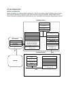
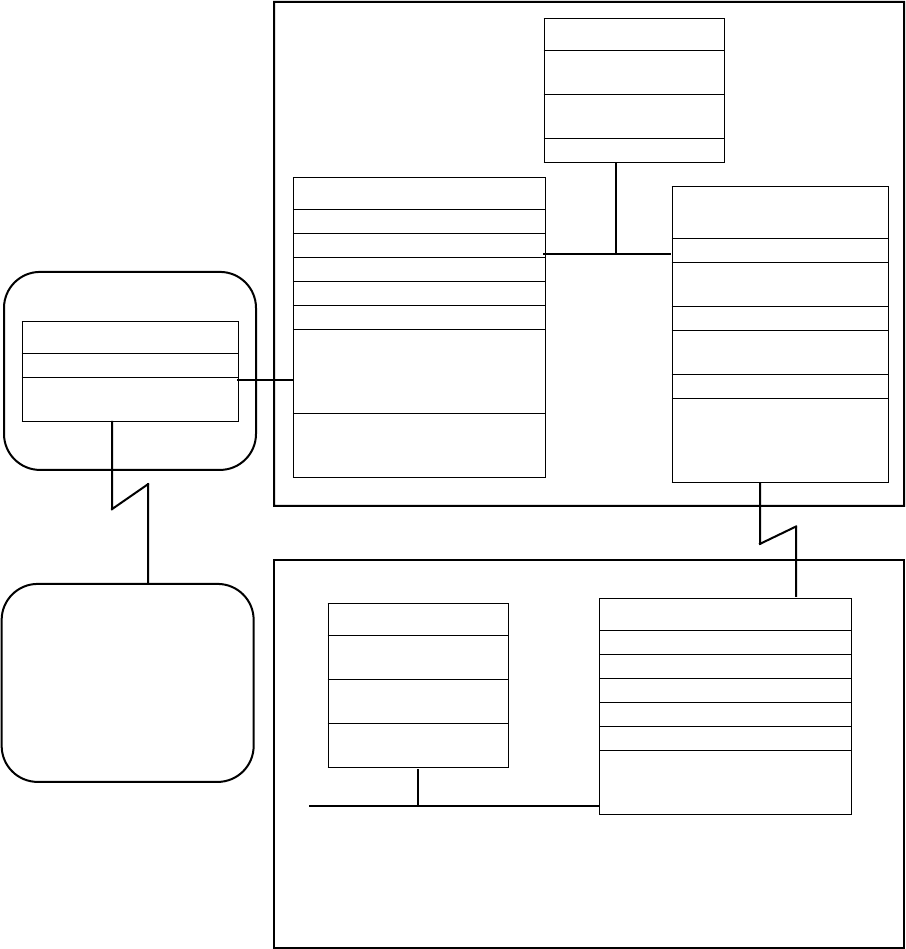
Below is a diagram of a simple network configuration. The ISP is providing a Class C address to the customer
site, and both networks A and B want to gain Internet access through this address. Netopia R5000 Series
Router B connects to Netopia R5000 Series Router A and is provided Internet access through Routers A and B.
Router A:
IP Address: 10.0.0.1
Subnet Mask:
255.255.255.0
Router B:
IP Address: 192.168.1.1
Subnet Mask: 255.255.255.128
Remote IP: 10.0.0.1
Remote Sub: 255.255.255.0
Gateway: 10.0.0.1
Static Route:
192.168.1.128 [network]
255.255.255.128 [mask]
192.168.1.2 [via router]
Usable IP Addresses available to
Customer Site A: 192.168.1.1 -->
192.168.1.126
Netopia R5000 Series Router
A:
IP Address: 192.168.1.2
Subnet Mask:
255.255.255.128
Remote IP: 192.168.1.129
Remote Sub:
255.255.255.128
Gateway: 192.168.1.1
Usable IP Addresses avail-
able to Customer Site A:
192.168.1.1 -->
192.168.1.126
PC 1:
IP Address:
192.168.1.3
Subnet Mask:
255.255.255.128
Gateway: 192.168.1.1
PC 2:
IP Address:
192.168.1.130
Subnet Mask:
255.255.255.128
Gateway:
192.168.1.129
Netopia R5000 Series B:
IP Address: 192.168.1.129
Subnet Mask: 255.255.255.128
Remote IP: 192.168.1.2
Remote Sub: 255.255.255.128
Gateway: 192.168.1.2
Usable IP Addresses available to
Customer Site B: 192.168.1.129
--> 192.168.1.254
ISP Network
Internet
Customer Site A
Customer Site B
LAN
LAN


