


iR1200 Modem
26 nextel.com
6 Mount the fuse holder by tie wrapping it to the other cabling
wires and dress wires as necessary.
7 Shorten the red lead of the DC power cable to remove any
excess length and crimp the fuse holder’s red lead to it using
the in-line splice.
8 Connect the ring tongue terminal from the fuse holder to the
positive (+) battery terminal.
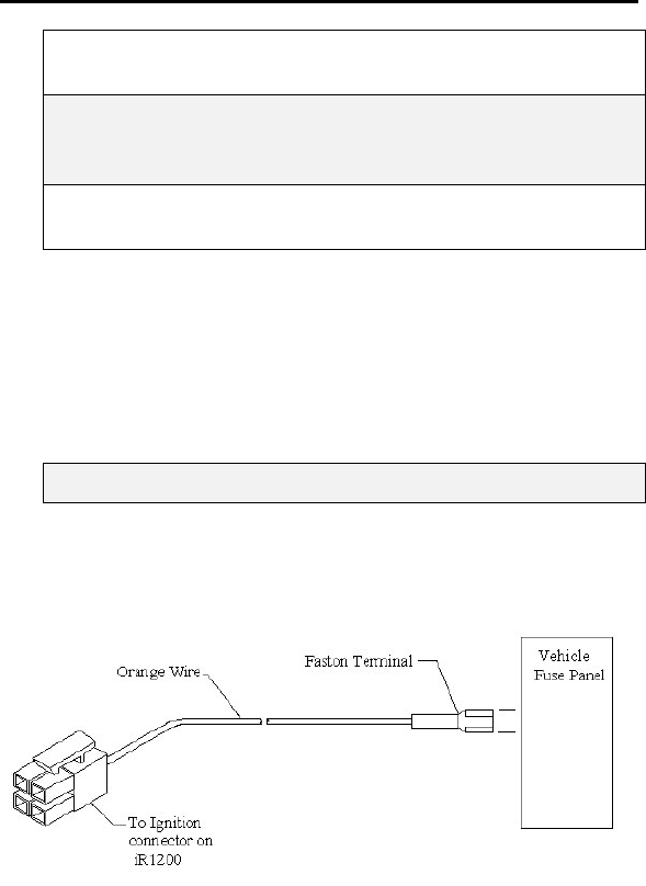
Route and Connect Ignition Cable
Approved Cable
The following DC power cable must be used (sold separately, see Accessories
Table for ordering information).
5100-C5-RFM – Vehicle Power Harness
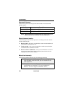
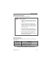
Route Cable
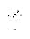
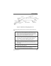
Route the Ignition cable using the following diagram as a guideline:
Figure 7 – Modem Power Wiring Diagram (Level 2)