


Verifying Installation
RFM-4200-5015 Rev1
39
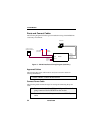
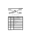
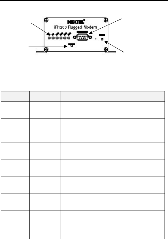
LED (signal indicators)
displays the modem’s
serial interface status.
Status LED
displays the
modem’s
iDEN network
status.
Diagnostic Connector
used to receive modem
diagnostic information.
Reset Button used to
power cycle the
modem and re-
establishes connection
to the network.
LED (signal indicators)
displays the modem’s
serial interface status.
Status LED
displays the
modem’s
iDEN network
status.
Diagnostic Connector
used to receive modem
diagnostic information.
Reset Button used to
power cycle the
modem and re-
establishes connection
to the network.
Figure 9 – iR1200 Front Panel Layout
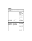
Signal Color Indication
Tx Blinking
Green
Modem is transmitting data to the
computer data terminal (DTE).
Rx Blinking
Green
Modem is receiving data from the
computer. Modem is receiving data from
the DTE.
RTS Green
(Off)
Request To Send from computer (DTE) is
asserted (not asserted).
CTS Green
(Off)
Clear To Send from modem is asserted
(not asserted).
DTR Green
(Off)
Data terminal equipment is ready (not
ready).
DSR Green
(Off)
Modem is ready (not ready).
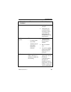
STATUS Solid Red The modem is searching for signal within
the Nextel network. If the modem status
changes from blinking green back to solid
red, the signal has been lost and the