


iR1200 Modem
34 nextel.com
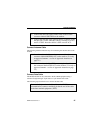
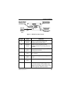
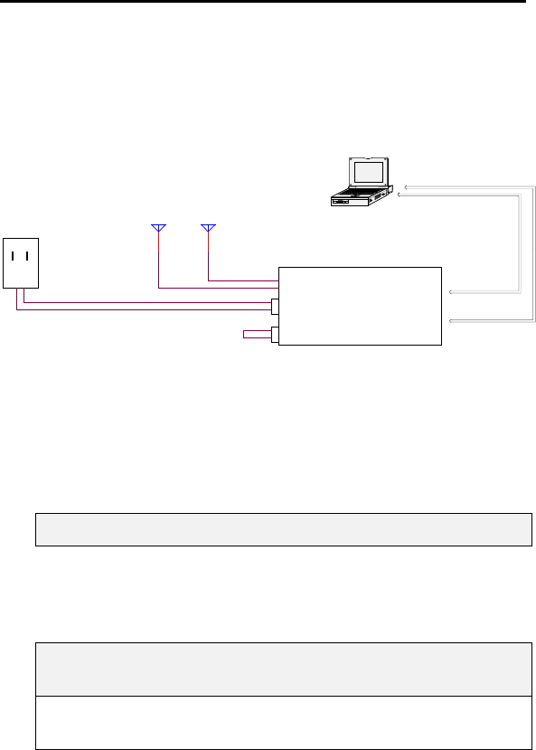
Route and Connect Cables
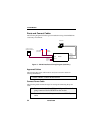
The following diagram illustrates typical installation wiring of the iR1200 into
a stationary environment.
Figure 8 – iR1200 Installation Wiring Diagram (Stationary)
Approved Cables
The following DC power cable must be used (see Accessories Table for
ordering information).
5100-C5-RFM – Vehicle Power Harness
Connect Power Cable
The following table contains the steps for routing and connecting the power
cable:
1 Connect male end of the AC Power Adapter cable to the 2-
prong connector labeled POWER on the modem.
2 Connect the free end of the power cable to a 120VAC-power
outlet.
COMPUTER
RS-232
GPS DATA
RS-232
MODEM DATA
120VAC TO 12VDC
POWER CONVERTER
MODEM
ANTENNA
IGNITION
BYPASS
PLUG
GPS ANTENNA
(OPTIONAL)
POWER
IGNITION
iR1200