


224 MG 1000B platform hardware installation
1
Fasten the right guide bracket to the right rack support.
a. Insert two #12-24 self-tapping screws into the two middle slots
in the guide bracket and into the respective holes in the right
rack support.
b. Tighten the screws. See Figure 69 "Guide bracket installed in a
rack" (page 224).
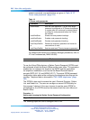
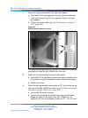
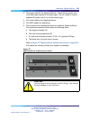
Figure 69
Guide bracket installed in a rack
The guide brackets guide the MG 1000B Core into place and enable
one person to install the MG 1000B Core in the rack.
2
Fasten the left guide bracket to the left rack support.
a. Insert two #12-24 self-tapping screws into the two middle slots in
the bracket and into the respective holes in the left rack support.
b. Fasten the screws.
3
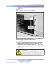
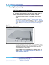
Attach the right ear bracket (marked with an "R") to the holes on the
right side of the MG 1000B Core. See Figure 70 "Right ear bracket
installed on the MG 1000B Core" (page 225).
a. Use two #8-32 machine screws.
b. Position the ear bracket so that the four holes on the bracket
flange are nearer to the back of the MG 1000B Core. To
determine the front of the bracket, locate the "R". This "R" must
Nortel Communication Server 1000
Branch Office Installation and Commissioning
NN43001-314 01.02 Standard
Release 5.0 20 June 2007
Copyright © 2007, Nortel Networks
.