


Connecting the MG 1000B Core to the network 247
Procedure 22
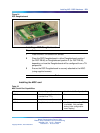
Connecting the Ethernet ports
Step Action
To configure the TLAN and ELAN network interfaces at the MG 1000B
Core and enable traffic over the LAN/WAN, connect the CAT5 cables and
configure the data connectivity.
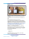
1 Insert the CAT5 cable into the RJ-45 10BaseT Port 1 or Ethernet
MAU. Connect the other end of the CAT5 cable to the switch. For
more information about the switch, see Converging the Data Network
with VoIP Fundamentals (NN43001-260).
This connects the MG 1000B Core to the ELAN network interface.
The switch connects to the LAN/WAN router.
2 Install and put the Signaling Server into operation, and connect the
Signaling Server ELAN and TLAN network interfaces to the switch.
See "MG 1000B platform hardware installation" (page 221).
For more detailed information on the switch and router connections, see
Converging the Data Network with VoIP Fundamentals (NN43001-260).
—End—
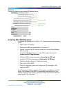
Using Element Manager to configure the node
In Element Manager, configure the following IP telephony node values that
are specific to the MG 1000B:
•
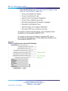
under H323 GW Settings (see Figure 89 "Confirm IP telephony node
values H.323 Gatekeeper" (page 248)):
— Primary gatekeeper IP address
— Alternate gatekeeper IP address (if equipped)
— Primary Network Connect Server IP address
— Primary Network Connect Server Port number
— Alternate Network Connect Server IP address
— Alternate Network Connect Server Port number
— Primary Network Connect Server time-out
If NRS and NCS have different IP addresses, then the Branch Office
must be configured as non-RAS H.323 endpoint with NCS support in
the NCS database.
Nortel Communication Server 1000
Branch Office Installation and Commissioning
NN43001-314 01.02 Standard
Release 5.0 20 June 2007
Copyright © 2007, Nortel Networks
.