


402 Appendix C On-net dialing plan configuration examples
•
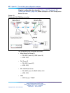
Call Server B
— DN: 3001 (zone 20)
— VNR: YES
•
MG 1000B Call Server
— DN: 3201 (zone 15, BUID 3201), 3101
— VNR: YES
•
NRS
— CDP Domain "TNDN"
— 3001 "CS_B"
— 3002 "MO"
— 3101 "BO"
— 3201 "MO"
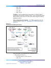
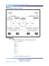
Call Scenario
The following is a general example of a call scenario after the move has
occurred, based on Figure 124 "Transferable DN (TNDN) (post-transfer)"
(page 401):
•
Alice (at Office B) calls Bob (at the Branch Office) by dialing DN 3201.
• The Call Server of Alice’s current office (Office B) recognizes 3201 as
a vacant number. VNR is enabled, so according to the RLI defined for
VNR, it uses the Virtual Trunk specified for that route.
•
The NRS is queried for a destination node IP address with which to route
the call over the Virtual Trunk. Because the NRS has been updated to
reflect the current location of "3201", the corresponding node IP address
of main office A is returned.
• The Destination Call Server terminates the incoming Virtual Trunk call
to DN 3201.
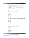
Configuration for TNDN
To configure TNDN, do the following:
Step Action
1
Configure VNR. VNR must be enabled at all Call Servers and MG
1000B SSCs.
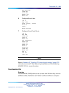
>LD 15
REQ: CHG
TYPE: CDB
Nortel Communication Server 1000
Branch Office Installation and Commissioning
NN43001-314 01.02 Standard
Release 5.0 20 June 2007
Copyright © 2007, Nortel Networks
.