


Installing an MG 1000B Core 227
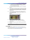
b. Follow the instructions in Telephony Manager 3.1 Installation
and Commissioning (NN43050-300). A sample pr intout of the
Ethernet configuration is provided.
Do not connect a serial port to the AUX connector. It can damage
the port.
13 Set DIP switches on the power supply for the desired ringing voltage,
ringing frequency, and message waiting voltage. These procedures
are in Communication Server 1000S: Installation and Configuration
(NN43031-310).
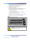
14
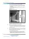
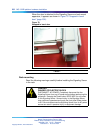
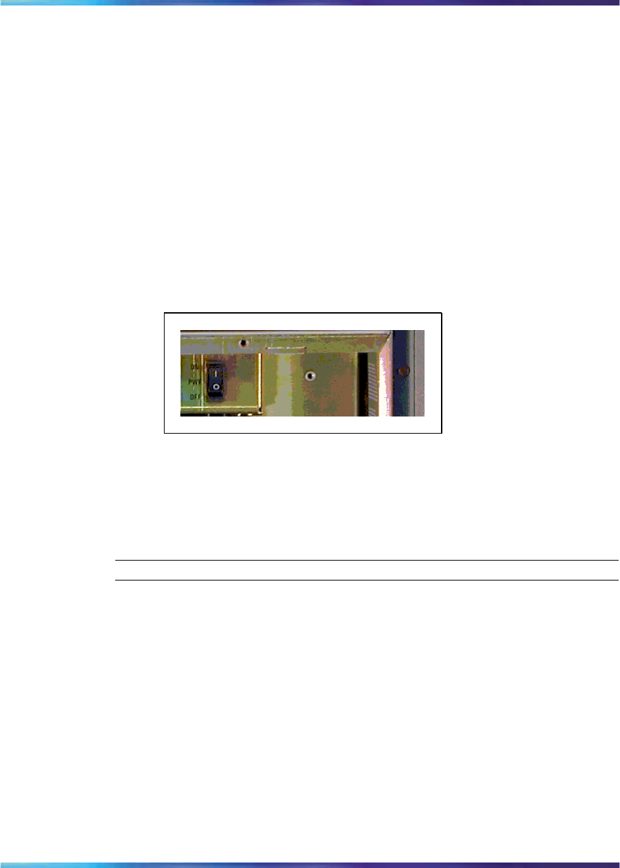
Connect the system to an AC power source. Make sure that the
source matches the label on the back of the MG 1000B Core. Turn
the power switch to "ON".
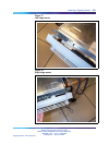
Figure 72
Power switch on the front of the MG 1000B Core
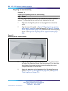
15
Install any remaining equipment, such as alarms. See
Communication Server 1000E: Installation and Configuration
(NN43041-310).
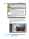
16
Reinstall the front covers on the MG 1000B Core and MG 1000B
Expander.
—End—
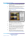
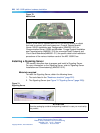
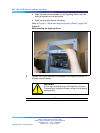
Installing cards
In the MG 1000B, install Media Cards. To install and configure the 8- or
32-port Media Card (see Figure 73 "Media Card" (page 228)) or the 24-port
ITG-P card, refer to IP Line Fundamentals (NN43100-500).
Nortel Communication Server 1000
Branch Office Installation and Commissioning
NN43001-314 01.02 Standard
Release 5.0 20 June 2007
Copyright © 2007, Nortel Networks
.