


Using the BayStack 410-24T 10BASE-T Switch
1-28
309985-B Rev 00
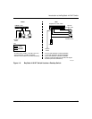
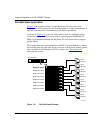
Cascade A Out Connector
Provides an attachment point for connecting this unit to another unit via the
cascade cable. A return cable from another unit’s Cascade A Out connector to this
unit’s Cascade A In connector completes the stack connection (see the example
shown in Figure 1-11
).
Unit Select Switch
The Unit Select switch (up = Base) determines the base unit for the stack
configuration (see “
Initial Installation” on page 1-29). The Unit Select switch
status is displayed on the BayStack 410-24T switch LED display panel. When the
Unit Select switch is in the Base (up) position, all other Unit Select switches in the
stack configuration must be set to Off (down).
Cascade A In Connector
Provides an attachment point for accepting a cascade cable connection from an
adjacent unit in the stack. A return cable from this unit’s Cascade A Out connector
to the adjacent unit’s Cascade A In connector completes the stack connection (see
the example shown in Figure 1-11
).
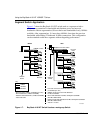
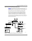
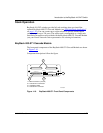
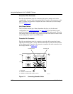
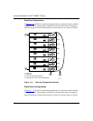
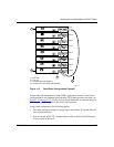
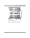
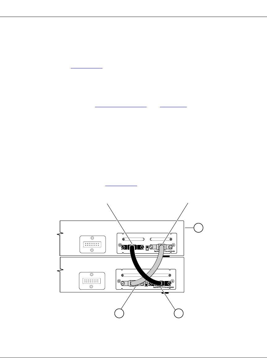
Figure 1-11. Connecting Cascade Cables
Cascade Module
Cascade A Out
Unit 1
Cascade A Out
Cascade A In
Unit 2
1 = Base unit
2 = 303978-A cascade cable
3 = 303978-A cascade cable (used for return)
BS41010A
Cascade A InUnit Select
Cascade A Out
Cascade A InUnit Select
32
1
Redundant Power
Redundant Power
Cascade Module