


Introduction to the BayStack 410-24T Switch
309985-B Rev 00
1-33
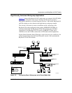
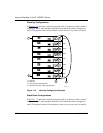
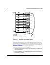
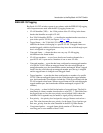
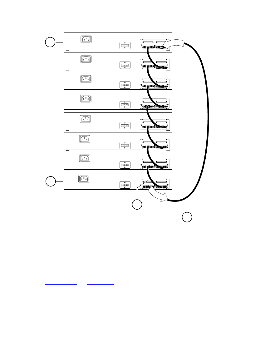
Figure 1-13. Stack Down Configuration Example
Certain network management station (NMS) applications assume a stack-down
configuration for the graphical user interface (GUI) that represents the stack (see
Figure 1-13
on page 1-33). For this reason, Nortel Networks recommends that you
always configure the top unit in the stack as the base unit.
In any stack configuration, the following applies:
• The entire stack powers up as a single logical unit within 30 seconds after the
base unit initialization.
• You can attach an RS-232 communications cable to the Console/Comm port
of any switch in the stack.
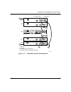
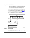
Unit 2
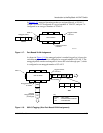
1 = Base unit
2 = Last unit
3 = Cascade cable (PN 303978-A)
4 = Cascade max-return cable (PN 303979-A)
BS41012A
Unit 1
Unit 4
Unit 3
Unit 6
Unit 5
Unit 8
Unit 7
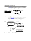
2
1
I
n
O
u
t
4
3