


Introduction to the BayStack 410-24T Switch
309985-B Rev 00
1-63
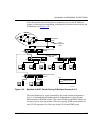
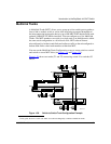
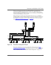
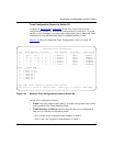
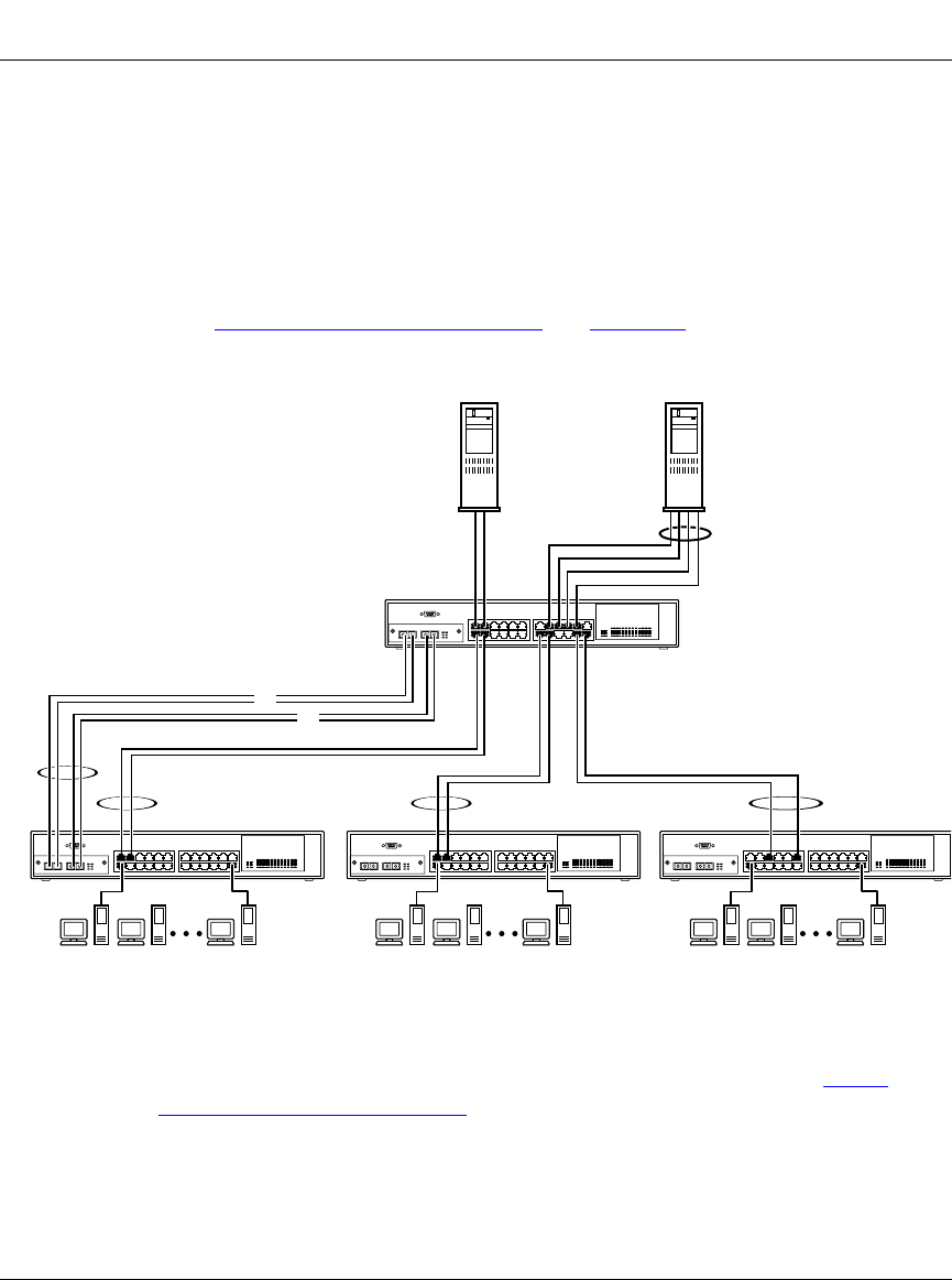
Clients accessing data from the servers (FS1 and FS2) are provided with
maximized bandwidth through trunks T1, T2, T3, T4, and T5. Trunk members
(the ports making up each trunk) do not have to be consecutive switch ports; they
can be selected randomly, as shown by T5.
With spanning tree enabled, one of the trunks (T2 or T3) acts as a redundant
(backup) trunk to switch S2. With spanning tree disabled, trunks T2 and T3 must
be configured into separate VLANs for this configuration to function properly
(see “I
EEE 802.1Q VLAN Workgroups” on page 1-36).
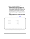
Figure 1-40. Client/Server Configuration Example
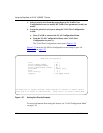
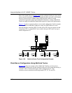
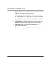
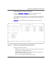
The trunk configuration screens for switches S1 to S4 are shown in “Trunk
Configuration Screen Examples” following this section. For detailed information
about configuring trunks, see “MultiLink Trunk Configuration” on page 3-57.
T2
S2
S3
T3 T4
F
S4
T5
F
S1
BS41033
A
FS1
FS2
T1