


Cabling the Switch
2-5
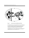
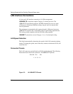
Dual V.35 WAN Interface (Optional)
The Dual V.35 WAN connectors are located on a PCI card that offers two separate
DB26S connectors that provide the signals needed to interface to V.35 equipment.
Included in the accessory box are two cables that map the DB26S signals to a
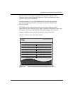
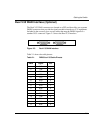
standard V.35 connector. Figure 2-3 shows the Dual V.35 interface.
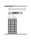
Figure 2-3. Dual V.35 WAN Interface
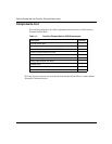
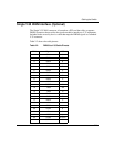
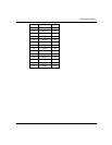
Table 2-1 shows the cable pinouts.
Table 2-1. DB26S-to-V.35 Cable Pinouts
DB26 Signal V.35
1GNDA
2TDAP
3 RDA R
4RTSC
5CTSD
6 DSR E
7GNDB
8 DCD F
9 RCB X
11 ETB W
12 TCB AA
14 TDB S
15 TCA Y
16 RDB T
17 RCA V