


Getting Started with the Contivity Extranet Switch 4500
2-10
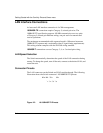
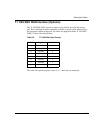
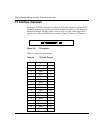
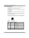
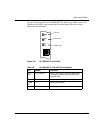
T3 Interface (Optional)
The Single T3 WAN connection is located on a PCI card which has a 50-pin SCSI
II female connector that provides the signals needed to interface to a T3 modem or
Modem Eliminator. Included in the accessory box is a cable, which maps the T3
signals out to a 50-pin SCSI II male connector. Figure 2-4 shows a T3 interface.
Figure 2-4. T3 Interface
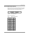
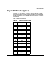
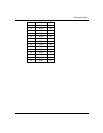
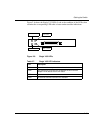
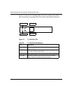
Table 2-4 shows the cable pinouts.
Table 2-4. T3 Cable Pinouts
J1 Signal J2
1GND1
2 RCB 2
3 CAB 3
4 RDB 4
5LCB5
6STB6
7GND7
8 TAB 8
9TTB9
10 LAB 10
11 TDB 11
12 LBB 12
13 GND 13
19 GND 19
24 TESTB 24
25 GND 25
26 GND 26