


Cabling the Switch
2-13
Serial Interface Cable (Optional)
Nortel Networks ships a serial cable with the Switch. Optionally, you can provide
the Switch with a Management IP Address, subnet mask, and default gateway
address among other things via the Serial Interface (refer to page 3-6 for details).
Nortel Networks, however, recommends that you use the IP Address
Configuration Utility diskette for easy initial IP address configuration (refer to
page 3-3 for details). Later, you can use the serial interface configuration menu to
perform management functions that you might need if problems were to arise.
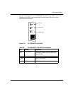
The serial cable provided with the Switch is a DB9/DB25-to-DB9/DB25. This
provides a crossover (transmit-to-receive and receive-to-transmit). The DB9
connector goes into the Switch and the other DB9 or DB25 connector goes into
your workstation. You should ignore the extra DB25 connection that
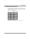
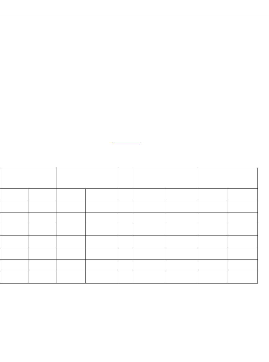
is attached to the Switch. Table 2-5
shows the multiple cable DB-9/DB25 serial
interface cable pinouts.
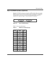
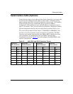
Table 2-5. Multi-DB-9 and DB-25 Connector Pinouts
Serial Port
DB-9 Connector
Serial Port
DB-25 Connector
Serial Port
DB-25 Connector
Serial Port
DB-9 Connector
Pinout Signal Pinout Signal Pinout Signal Pinout Signal
2 RXD 3 TXD > 2 RXD 3 TXD
3 TXD 2 RXD > 3 TXD 2 RXD
4 DTR 20 DSR > 6 DTR 6 DSR
5 Ground 7 Ground > 7 Ground 5 Ground
6 DSR 6 DTR > 20 DSR 4 DTR
7 RTS 4 RTS > 5 CTS 8 CTS
8 CTS 5 CTS > 4 RTS 7 RTS