


Mediant 2000 SIP User’s Manual 2. Mediant 2000 Physical Description
Version 4.4 19 July 2005
2 Mediant 2000 Physical Description
This section provides detailed information on the Mediant 2000 hardware components, the
location and functionality of the LEDs, buttons and connectors on the front and rear panels.
2.1 General
The Mediant 2000 gateway comprises the following hardware components:
• A 19-inch 1U high rack mount chassis (refer to Section
2.2 on page 20).
• A single compactPCI™ TP-1610 board (refer to Section
2.3 on page 20).
• A single TP-1610 Rear Transition Module (RTM) (refer to Section
2.4 on page 24).
• A single available cPCI slot for an optional third-party CPU board (refer to Section
2.5 on
page 25).
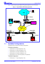
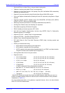
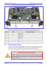
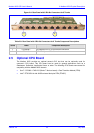
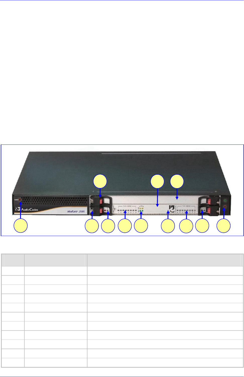
Figure
2-1 shows the front view of the Mediant 2000 media gateway.
Figure
2-1: Mediant 2000 Front View
Table
2-1: Mediant 2000 Front View Component Descriptions
Item # Label Component Description
1 FAULT Dual AC Power LED.
2 cPCI board locking screws.
3 cPCI latches.
4 TP-1610 cPCI board, 16-trunk configuration.
5 Status LED Indicators.
6 T1/E1 STATUS E1/T1 Trunk Status LED Indicators.
7 ETH Ethernet LED Indicators.
8 Reset button.
9 cPCI LED Indicators.
10 Power and Fan LEDs
11 An available cPCI slot for an optional third-party CPU board.
1 7
2
3
6
5
4
8
6
9
10
11