


Mediant 2000 SIP User’s Manual 3. Installing the Mediant 2000
Version 4.4 31 July 2005
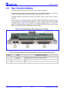
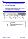
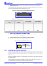
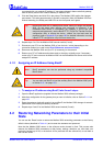
Figure 3-4: Mediant 2000 Rear Panel Cabling (8 Trunks, DC Power))
Table
3-2: Mediant 2000 Rear Panel Cabling (8 Trunks, DC Power) Component Descriptions
Item # Label Component Description
1 RTM latches.
2 ETH A Category 5 network cable, connected to the Ethernet 1 RJ-45 port.
3 PSTN 8 RJ-48c ports, each supporting a trunk.
4
Protective earthing screw.
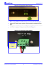
5 48V 4A max 2-pin connector for DC.
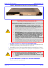
Electrical Earthing
The unit must be permanently connected to earth via the screw provided at the back on
the unit. Use 14-16 AWG wire and a proper ring terminal for the earthing.
To cable the Mediant 2000, take these 4 steps:
1. Permanently connect the device to a suitable earth with the protective earthing screw on the
rear connector panel, using 14-16 AWG wire.
2. Connect the E1/T1 trunk interfaces (refer to Section
3.4.1 below).
3. Install the Ethernet connection (refer to Section
3.4.2 on page 32).
4. Connect the power supply (refer to Section
3.4.3 on page 33).
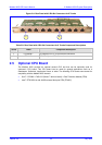
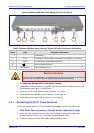
3.4.1 Connecting the E1/T1 Trunk Interfaces
Connect the Mediant 2000 E1/T1 Trunk Interfaces using either Telco or RJ-48 connectors:
With 50-pin Telco connectors (16-trunk device), take these 3 steps:
1. Attach the Trunk cable with a 50-pin male Telco connector to the 50-pin female Telco
connector labeled “Trunks 18” on the Rear Transition Module (RTM).
2. Connect the other end of the Trunk cable to the PBX/PSTN switch.
5
2
4
3
1 13