– 54 –
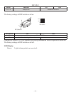
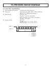
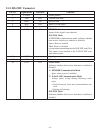
13-2. RS-232C Connector
Pin No. Signal name Direction Function
1 F-GND — Frame ground
2 TXD OUT Transmission data
3 RXD IN Receive data
4 RTS OUT Same as DTR signal.
5 N/C Not used
6 DSR IN STAR Mode
Status of this signal is not checked.
ESC/POS Mode
In DTR/DSR communication mode, indicates whether
data receive from host is enabled or disabled.
Space: Receive enabled
Mark: Receive disabled
(except when transmitting data by DLE EOT, and GS a)
This signal is not checked in the X-ON/X-OFF com-
munication mode.
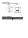
7 S-GND — Signal ground
8~19
N/C Not used
20
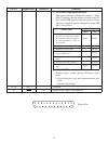
DTR OUT STAR Mode
Indicates whether data receive from host is enabled or
disabled.
1) DTR/DSR Communication Mode
Space when receive is enabled.
2) X-On/X-Off
Communication Mode
Always space, except during following condi
-
tions:
• Period between reset and communication ena
-
bled
• During self printing
ESC/POS Mode
Indicates whether data receive from host is enabled or
disabled.


