


CONTENTS
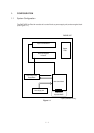
1. CONFIGURATION ..................................................................................... 1 - 1
1.1 System Configuration ........................................................................ 1 - 1
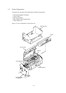
1.2. Printer Configuration.......................................................................... 1 - 2
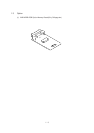
1.3 Option................................................................................................. 1 - 3
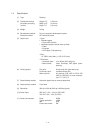
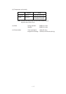
1.4 Specification ...................................................................................... 1 - 4
1.5 Safety Standards ............................................................................... 1 - 6
1.5.1 Certification Label.................................................................................... 1 - 6
1.5.2 Warning Label ......................................................................................... 1 - 6
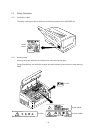
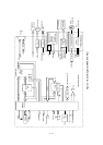
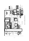
2. OPERATION DESCRIPTION .................................................................... 2 - 1
2.1 Main Control Board............................................................................ 2 - 4
2.2 Power Supply Unit ............................................................................. 2 - 5
2.3 High-Voltage Power Supply Board .................................................... 2 - 5
2.4 Electro-Photographic Processor ........................................................ 2 - 7
2.5 Electro-Photographic Process ........................................................... 2 - 11
2.5.1 Explanation of Each Process Operation.................................................. 2 - 13
2.6 Paper Jam Detection ......................................................................... 2 - 19
2.7 Toner Low Detection.......................................................................... 2 - 21
2.8 Cover Open ....................................................................................... 2 - 22
3. PARTS REPLACEMENT ........................................................................... 3 - 1
3.1 Precautions for Parts Replacement ................................................... 3 - 1
3.2 Parts Layout....................................................................................... 3 - 3
3.3 Replacing Parts ................................................................................. 3 - 6
3.3.1 Hopper Plate ........................................................................................... 3 - 6
3.3.2 LED Head and Head Spring .................................................................... 3 - 7
3.3.3 Transfer Roller ......................................................................................... 3 - 8
3.3.4 Upper Cover Assy ................................................................................... 3 - 9
3.3.5 High-Voltage Power Supply Board .......................................................... 3 - 10
3.3.6 Top Cover Assy and Flat Cable Assy...................................................... 3 - 11
3.3.7 Paper Holder ........................................................................................... 3 - 12
3.3.8 Side Plate M and Idle Gear ..................................................................... 3 - 13
3.3.9 Heat Assy ................................................................................................ 3 - 14
3.3.10 Drive Shaft E (Eject) and Eject Roller ..................................................... 3 - 17
3.3.11 Pressure Roller B (Back Up Roller) ......................................................... 3 - 18
3.3.12 Separator Guide ...................................................................................... 3 - 19
3.3.13 Pulse Motor (Main) .................................................................................. 3 - 21
3.3.14 Hopping Shaft Assy ................................................................................. 3 - 22
3.3.15 Resist Roller ............................................................................................ 3 - 23
3.3.16 Paper Sensor E, Paper Sensor Exit and Toner Sensor Assy ................. 3 - 24
3.3.17 Base Plate ............................................................................................... 3 - 25