


Where:
"*" is the selected Recognition Character. You may select any ASCII table symbol from
"!" (HEX address "21") to the right-hand brace (HEX "7D") except for the caret "^", "A",
"E", which are reserved for bus format request.
"ccc" stands for the hex-ASCII Command Class letter (one of eleven given in Table 4.1),
followed by the two hex-ASCII Command Suffix characters identifying the meter data,
features, or menu items to which the command is directed.
"<data>" is the string of characters containing the variable information the computer is
sending to the meter. These data (whether BCD or binary) are encoded into hex-ASCII
character (see Appendix D for binary-hex-ASCII chart), two characters to the byte.
Square brackets [indicating optional status] enclose this string, since some commands
contain no data.
"<nn>" are the two ASCII characters for the device Bus Address of RS485
communication.
Use values from "00" to hex "C7" (199 decimal).
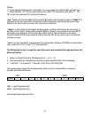
The following format is used for each byte sent and received through serial port of
Ethernet Server:
1. Seven or Eight-bit binary, Hexadecimal (0 ... 9, A ... F)
2. Two hexadecimal characters contained in each eight-bit field of the message
3. 1 start bit; 7 or 8 data bit; 1 Stop Bit; Odd, Even (No Parity) Bit
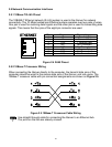
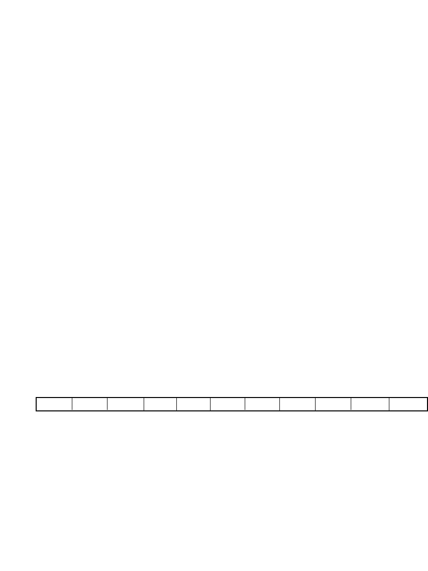
The figure below shows the bit sequences when a byte is transmitted or received
through the Ethernet Server.
LSB MSB
LSB – Least Significant bit
MSB – Most Significant bit
Least Significant beat sent first
13
START 1 2 3 4 5 6 7 8 STOP PARITY