


5
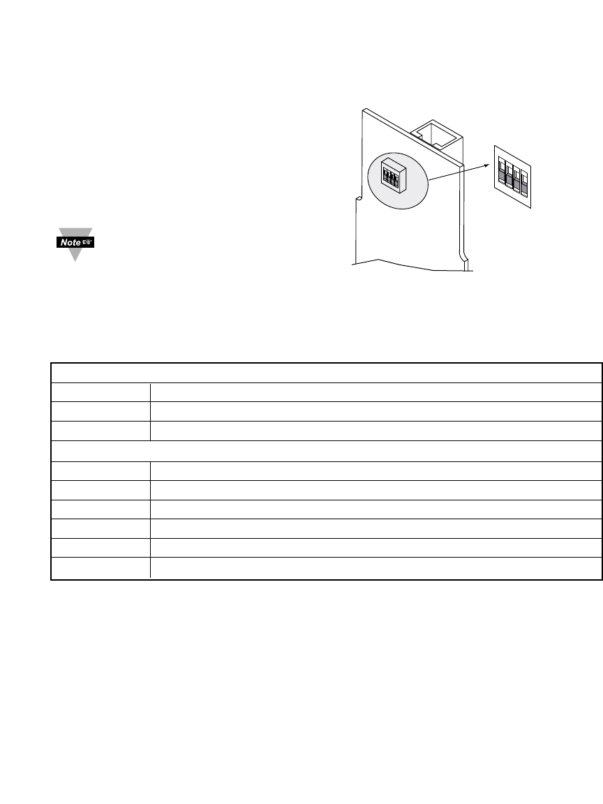
2.3 DIP Switches on the iServer
For Dipswitch access you must remove the main board from the case. Refer to the
Disassembly Instructions in your iLD Big Display Monitor/Controller Quickstart Manual.
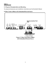
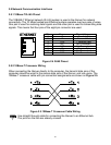
Figure 2.2 DIP Switches on the iServer
Table 2.1 Rear Panel Annunciators
Serial Communication Interface Section (For Models with RS485):
TB4 Pin 3 -Rx/Tx
TB4 Pin 2 +Rx/Tx
TB4 Pin 1 Return, Common Ground Shield connection
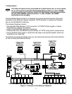
Network Communication Interface Section:
ETHERNET RJ45 interface for 10BASE-T connection.
RESET Button: Used for power reseting the iServer.
COL / ACTIVITY LED (Red) Blinking: Indicates network activities (receiving or sending packets).
ON / NET LINK LED (Green) Solid: Indicates good network link.
TX LED (Yellow) Blinking: Indicates transmitting data to the serial port.
RX LED (Green) Blinking: Indicates receiving data on the serial port.
1
4
3
2
OFF
ON
1
4
3
2
OFF
ON
The iServer is shipped with all DIP
switches in "OFF" position
1 To change the IP address
from the serial port
2 To change to default factory
settings
3 To enable/disable DHCP
4 To enable/disable Terminal
Server function