


12-9
Specifications
12
Item Specifications
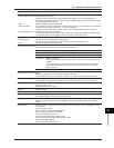
Bar graph display Displays the measured value on a bar graph.
Relationship between the digital display and bar graph
Displays the same channel on the digital display and bar graph. On the 2-channel digital + 2-
channel bar graph display, the top bar graph is the left digital display channel and the bottom graph
is the right digital display channel.
Scale Displays 10 equally spaced scale marks.
Alarm point mark For a channel set to delta computation, the alarm point marks of h and l are displayed. For all other
channels, the alarm point marks of H, L, T, and t are displayed.
• Blinks on the bar graph when an alarm occurs. Stops blinking when the alarm is released.
Bar graph display mode Selectable from the two modes below.
• Set the base point of the bar graph to the left or right of the recording span whichever is smaller in value.
• Set the base point of the bar graph to the 50% position of the recording span.
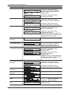
Flag display Displays measured values using flags.
Display channel The flag can be turned ON/OFF for each channel.
Flag (If flags overlap, the channel with the smallest number is displayed on top)
Scale Displays 10 equally spaced scale marks.
Channel alarm status display
Lists the alarm status of all channels using the symbols below.
Symbol Description
• Alarm is not set.
– Alarm is not occurring.
Channel No. Alarm is occurring.
Displays the channel number when an alarm occurs and clears when the alarm is
released.
If the alarm indication is set to hold operation, the indicator blinks when an alarm
occurs. When alarm ACK operation is performed, the indicator turns ON (stop
blinking) or OFF.
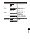
Date/time and chart speed display
Displays the date/time on the left and chart speed on the right.
The date display format can be selected. The format is common with the “Date printout format.”
DI/DO status display DI: Displays the ON/OFF state of the remote control input terminal (/R1 option).
DO: Displays the relay operation (active) of the alarm output terminal (/A1, /A2, or /A3 option).
Status display Displays the status below. The display condition is the same as the status display under the main
display (see page 12-7).
Alarm and chart end (/F1 option)
Lights off Displays nothing.
Skip Skips the screen during screen switching.
Tag display Displays 7-digit tags in place of channel numbers.
See the digital display and bar graph display sections.
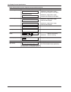
Multiple display (display in which different screens can be assigned to the top and bottom sections)
8 display types (see page 12-7) can be assigned to the top and bottom sections of the display
(VFD).
System display Displays system information by switching screens every 3 seconds. The main displayed contents
are as follows:
Analog: Number of inputs
Option1, Option2: Options that are installed
Math: Number of computation channels
Periodic: Periodic printout interval
Interval: Trend recording interval (dot model)
POC: Pen offset compensation ON/OFF (pen model)
MAC address: MAC address
Version: Firmware version number
12.4 Display Function Specifications